Community project
Vehicle Detection Module
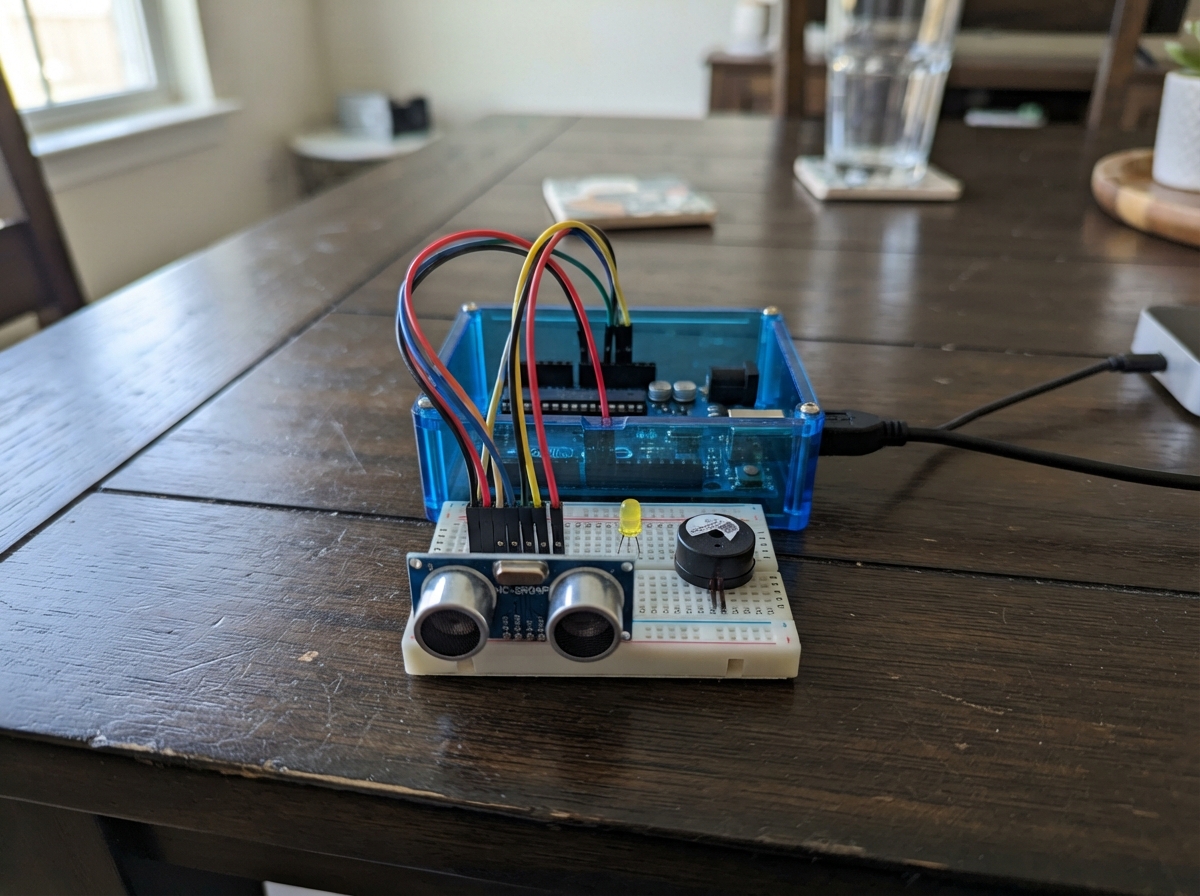
This vehicle detection module uses an ultrasonic distance sensor to monitor approaching traffic and trigger an audio warning when vehicles enter a danger zone. Built around an ESP32 microcontroller, the system continuously measures distance to nearby objects and activates a buzzer when a vehicle comes within 150 centimeters, providing real-time alerts for road safety applications.
The guide includes a complete wiring diagram showing how to connect the HC-SR04P ultrasonic sensor and buzzer to the ESP32, a full parts list, ready-to-flash firmware with configurable detection thresholds, and step-by-step assembly instructions. Builders will learn how ultrasonic ranging works, how to interface sensors with the ESP32, and how to implement responsive audio alerts for proximity detection.
Wiring diagram

Gather all the parts
Assemble it in 5 steps
1. Place the sensor facing approaching traffic
Mount the HC-SR04P so its two round ultrasonic openings face the lane where a vehicle approaches. Keep both openings clear of the enclosure and point the sensor straight across the measurement path.
- Mount it at a fixed height and aim it at a broad, flat part of the vehicle for steadier distance readings.
- Do not cover either round opening with tape, glue, or a panel; blocked openings prevent the sensor from measuring distance.
2. Connect sensor power
With the ESP32 unplugged, connect the HC-SR04P VCC pin to the ESP32 3V3 pin (power), then connect HC-SR04P GND to an ESP32 GND pin (ground).
- Use a red jumper for VCC and a black jumper for GND so the power wires are easy to check.
- Make sure VCC and GND are not swapped — swapped power can damage the sensor.
3. Connect the measuring signals
Connect HC-SR04P TRIG to ESP32 GPIO27 (signal that starts each distance measurement). Connect HC-SR04P ECHO to ESP32 GPIO26 (signal that returns the measured distance).
- The HC-SR04P is the 3.3 V-compatible version, so its ECHO signal can connect directly to GPIO26.
- Do not substitute a common 5 V-only HC-SR04 in this wiring; its 5 V ECHO signal can damage the ESP32 input without a level shifter.
4. Wire the Audio Warning buzzer
Connect the buzzer SIGNAL pin to ESP32 GPIO4 (Audio Warning control), then connect its GND pin to an ESP32 GND pin (ground). Place the buzzer where people at the crossing can hear it, while keeping it protected from rain.
- GPIO4 turns the buzzer on only when the ESP32 decides a vehicle is inside the danger zone.
- Use a small 3.3 V-compatible active buzzer. A high-power buzzer must not be connected directly to GPIO4 because it can overload the ESP32 pin.
5. Check the vehicle-warning path
Confirm the complete logical path is Vehicle → HC-SR04P → Distance Measurement → ESP32 checks the 150 cm danger-zone threshold → Audio Warning buzzer. The buzzer sounds only while a valid measurement says a vehicle is 150 cm or closer.
- Keep the sensor fixed after aiming it; moving the sensor changes the measured distance.
Review all connections
1. Connections between "vehicle_ultrasonic_sensor" and "ESP32"
2. Connections between "audio_warning_buzzer" and "ESP32"
Deploy the firmware
#include <Arduino.h>

// SmartJalan UNITEN — vehicle detection subsystem only.
// Data flow: approaching vehicle -> HC-SR04P -> distance measurement -> ESP32.

// Forward declarations
float measureDistanceCm();

constexpr uint8_t TRIG_PIN = 27;
constexpr uint8_t ECHO_PIN = 26;
constexpr uint8_t BUZZER_PIN = 4;  // Audio Warning buzzer signal.
constexpr float DANGER_ZONE_CM = 150.0f;
constexpr unsigned long SAMPLE_INTERVAL_MS = 200;
constexpr unsigned long ECHO_TIMEOUT_US = 30000;

bool lastDangerZoneState = false;
bool haveValidReading = false;
unsigned long lastSampleMs = 0;

float measureDistanceCm() {
  digitalWrite(TRIG_PIN, LOW);
  delayMicroseconds(2);
  digitalWrite(TRIG_PIN, HIGH);
  delayMicroseconds(10);
  digitalWrite(TRIG_PIN, LOW);

  const unsigned long echoDurationUs = pulseIn(ECHO_PIN, HIGH, ECHO_TIMEOUT_US);
  if (echoDurationUs == 0) {
    return -1.0f;
  }

  // Sound travels to the vehicle and back, so divide by two.
  return (echoDurationUs * 0.0343f) / 2.0f;
}

void setup() {
  Serial.begin(115200);
  pinMode(TRIG_PIN, OUTPUT);
  pinMode(ECHO_PIN, INPUT);
  pinMode(BUZZER_PIN, OUTPUT);
  digitalWrite(TRIG_PIN, LOW);
  digitalWrite(BUZZER_PIN, LOW);
  Serial.println("SmartJalan vehicle detection ready");
}

void loop() {
  const unsigned long now = millis();
  if (now - lastSampleMs < SAMPLE_INTERVAL_MS) {
    return;
  }
  lastSampleMs = now;

  const float distanceCm = measureDistanceCm();
  if (distanceCm < 0.0f) {
    digitalWrite(BUZZER_PIN, LOW);
    if (haveValidReading) {
      Serial.println("Distance Measurement: no echo received — Audio Warning off");
      haveValidReading = false;
    }
    return;
  }

  const bool inDangerZone = distanceCm <= DANGER_ZONE_CM;
  if (!haveValidReading || inDangerZone != lastDangerZoneState) {
    Serial.print("Distance Measurement: ");
    Serial.print(distanceCm, 1);
    Serial.print(" cm — ");
    Serial.println(inDangerZone ? "VEHICLE IN DANGER ZONE" : "vehicle outside danger zone");
  }

  // Vehicle detected → distance measured → threshold checked → Audio Warning.
  digitalWrite(BUZZER_PIN, inDangerZone ? HIGH : LOW);

  lastDangerZoneState = inDangerZone;
  haveValidReading = true;
}
Remix this project
Make it yours in one click
Open a full copy of this project in your own Schematik workspace — diagram, code, parts, and assembly steps included. Swap the sensor, add features, or redesign the whole thing with AI. The author's original stays untouched.