Community project
We Are Making Maze Solver Items Are Listed
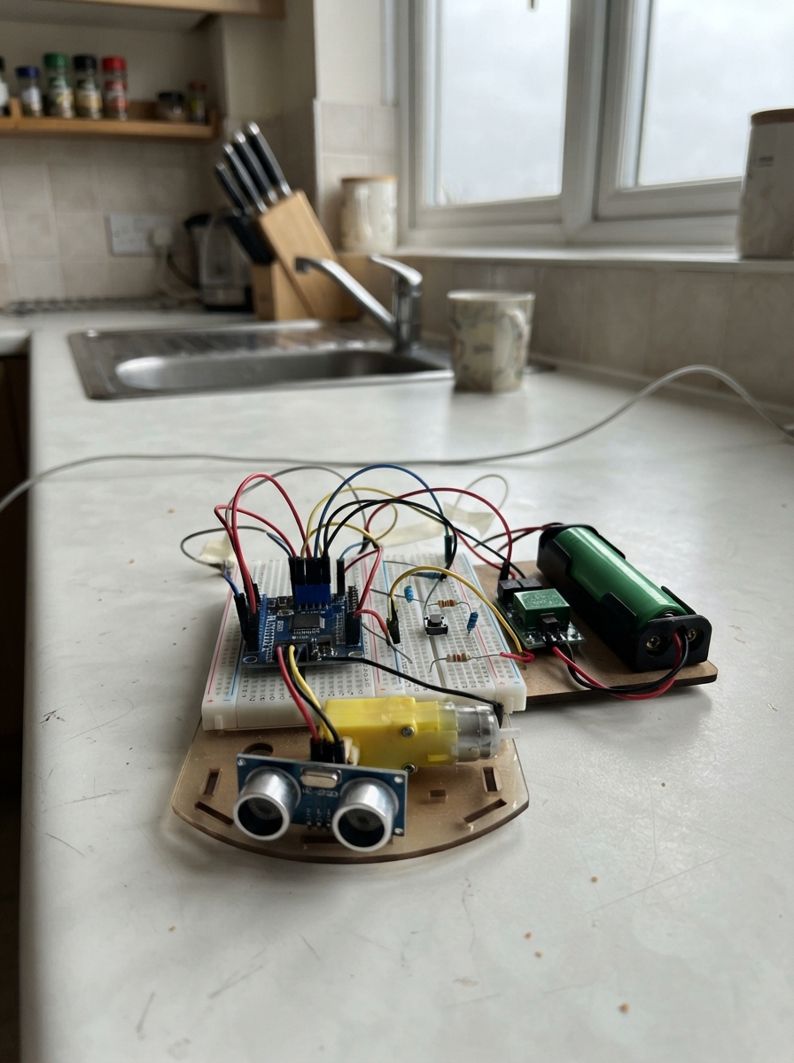
This project builds an autonomous maze-solving robot using an ESP32 microcontroller, dual TT geared motors, and three HC-SR04 ultrasonic distance sensors. The robot navigates mazes by following walls on its left side and detecting obstacles ahead, turning away when it encounters barriers. The guide provides a complete wiring diagram, parts list, and step-by-step assembly instructions for integrating the TB6612FNG motor driver, power distribution, and sensor connections.
The firmware implements wall-following logic with obstacle avoidance, controlled by a push button to start and stop the robot. Builders will learn how to configure the 24V buck converter for safe 5V operation, wire multiple sensors to the ESP32's GPIO pins, and tune motor speeds and distance thresholds for reliable maze exploration. A guided first-power test ensures all connections are safe before autonomous operation begins.
Wiring diagram

Gather all the parts
Assemble it in 7 steps
1. Set the converter to 5 V first
Keep the two 18650 cells out of the holder. Use a meter on the buck converter output and turn its small adjustment screw until VOUT+ to VOUT− reads 5.0 V. Do this before connecting the ESP32, sensors, or motor driver.
- Mark the converter output wires red for VOUT+ and black for VOUT− so they do not get mixed up later.
- Do not connect the 7.4 V battery pack directly to the ESP32, HC-SR04 sensors, or TT motors; the higher voltage can damage them.
2. Make the shared power lines
Connect battery holder BAT+ to buck converter VIN+ and battery holder BAT− to VIN−. From the converter, make one red 5 V line from VOUT+ and one black ground line from VOUT−. Connect the red 5 V line to ESP32 VIN/5V, TB6612 VM, and every HC-SR04 VCC. Connect the black ground line to ESP32 GND, TB6612 GND, and every HC-SR04 GND.
- Every part must share the same black ground line, otherwise the control signals cannot be understood.
- Use the ESP32 pin marked VIN or 5V, not the 3V3 pin, for the converter's 5 V output.
- Make sure VOUT+ and VOUT− are not swapped — reversed power can damage the ESP32, sensors, and driver.
3. Wire the motor driver and motors
Connect TB6612 VCC to ESP32 3V3. Connect AIN1 to GPIO16, AIN2 to GPIO17, PWMA to GPIO18, BIN1 to GPIO19, BIN2 to GPIO21, PWMB to GPIO22, and STBY to GPIO23. Connect AO1 to the left motor M1 and AO2 to left motor M2. Connect BO1 to right motor M1 and BO2 to right motor M2.
- If a wheel spins backwards during testing, swap that motor's two wires at AO1/AO2 or BO1/BO2.
- Keep the motor wires away from the sensor signal wires where possible.
- Do not connect either TT motor directly to an ESP32 GPIO pin; the motor current can damage the board.
4. Wire the front distance sensor safely
Connect the front HC-SR04 TRIG pin to GPIO25. Connect its ECHO pin to one leg of the front 10 kΩ resistor. Join the other leg of that 10 kΩ resistor, one leg of the front 20 kΩ resistor, and ESP32 GPIO34 in the same breadboard row. Connect the remaining leg of the 20 kΩ resistor to the black ground line.
- The joined resistor legs and GPIO34 make a safe meeting point that reduces the sensor's 5 V ECHO signal before it reaches the ESP32.
- Never connect an HC-SR04 ECHO pin directly to an ESP32 pin — its 5 V signal can damage the 3.3 V ESP32 input.
5. Wire the left and right distance sensors
For the left HC-SR04, connect TRIG to GPIO26; connect ECHO through its 10 kΩ resistor to a shared row with GPIO35 and one leg of its 20 kΩ resistor; connect the other 20 kΩ leg to ground. For the right HC-SR04, connect TRIG to GPIO27; connect ECHO through its 10 kΩ resistor to a shared row with GPIO36 and one leg of its 20 kΩ resistor; connect the other 20 kΩ leg to ground.
- Each sensor needs its own pair of resistors; do not join the three ECHO signal rows together.
- Mount the front sensor facing forward, with the other two facing left and right.
- A loose ground wire can make the distance readings jump or stop working.
6. Wire the start button
Connect one side of the push button to ESP32 GPIO32 and the opposite side to the black ground line. If your small button has four legs, use two legs on opposite sides of the button, not two legs on the same side.
- The program uses the ESP32's built-in pull-up, so no extra resistor is needed for this button.
- Pressing the button once starts the robot and pressing it again stops it.
- Do not connect the button signal to the 5 V line; GPIO32 is a 3.3 V input.
7. Do a safe first power test
Lift the robot so both wheels are off the table. Insert the two cells in the correct direction shown on the holder, then plug the ESP32 into USB for programming. Press the button once and check that the wheels and sensor directions match their positions before placing the robot in a maze.
- If the robot drives in the wrong direction, swap only the two wires of the motor that is backwards.
- Use protected, matched rechargeable 18650 cells and charge them with a proper 2-cell lithium-ion charger.
- Do not short the battery holder's red and black leads together; lithium-ion cells can supply enough current to heat wires quickly.
Review all connections
1. Connections between "battery_holder" and "ESP32"
2. Connections between "buck_converter" and "ESP32"
3. Connections between "motor_driver" and "ESP32"
4. Connections between "front_sensor" and "ESP32"
5. Connections between "front_echo_upper" and "ESP32"
6. Connections between "front_echo_lower" and "ESP32"
7. Connections between "left_sensor" and "ESP32"
8. Connections between "left_echo_upper" and "ESP32"
9. Connections between "left_echo_lower" and "ESP32"
10. Connections between "right_sensor" and "ESP32"
11. Connections between "right_echo_upper" and "ESP32"
12. Connections between "right_echo_lower" and "ESP32"
13. Connections between "start_button" and "ESP32"
Deploy the firmware
#include <Arduino.h>
// ARES-M basic maze explorer for ESP32 DevKit v1
// It starts and stops with the button, keeps the left side near a wall,
// and turns away when the front sensor sees a nearby wall.


// Forward declarations
long distanceCm(int trigPin, int echoPin);
void setMotor(int in1, int in2, int pwmPin, int speedValue);
void drive(int leftSpeed, int rightSpeed);
void stopMotors();
void moveFor(unsigned long moveTime, int leftSpeed, int rightSpeed);
void turnLeft90();
void turnRight90();
void updateStartButton();

const int LEFT_IN1 = 16;
const int LEFT_IN2 = 17;
const int LEFT_PWM = 18;
const int RIGHT_IN1 = 19;
const int RIGHT_IN2 = 21;
const int RIGHT_PWM = 22;
const int DRIVER_STBY = 23;

const int FRONT_TRIG = 25;
const int FRONT_ECHO = 34;
const int LEFT_TRIG = 26;
const int LEFT_ECHO = 35;
const int RIGHT_TRIG = 27;
const int RIGHT_ECHO = 36;
const int START_BUTTON = 32;

const int MOTOR_SPEED = 170;       // 0 to 255
const int TURN_SPEED = 165;
const int WALL_DISTANCE_CM = 18;
const int OPENING_DISTANCE_CM = 28;
const unsigned long CELL_MOVE_MS = 260;
const unsigned long TURN_90_MS = 330;

bool running = false;
bool lastButtonReading = HIGH;
bool stableButtonState = HIGH;
unsigned long lastDebounceTime = 0;

long distanceCm(int trigPin, int echoPin) {
  digitalWrite(trigPin, LOW);
  delayMicroseconds(3);
  digitalWrite(trigPin, HIGH);
  delayMicroseconds(10);
  digitalWrite(trigPin, LOW);

  unsigned long duration = pulseIn(echoPin, HIGH, 25000UL);
  if (duration == 0) return 400; // no echo means clear space for this simple explorer
  return duration / 58;
}

void setMotor(int in1, int in2, int pwmPin, int speedValue) {
  speedValue = constrain(speedValue, -255, 255);
  if (speedValue > 0) {
    digitalWrite(in1, HIGH);
    digitalWrite(in2, LOW);
  } else if (speedValue < 0) {
    digitalWrite(in1, LOW);
    digitalWrite(in2, HIGH);
  } else {
    digitalWrite(in1, LOW);
    digitalWrite(in2, LOW);
  }
  analogWrite(pwmPin, abs(speedValue));
}

void drive(int leftSpeed, int rightSpeed) {
  digitalWrite(DRIVER_STBY, HIGH);
  setMotor(LEFT_IN1, LEFT_IN2, LEFT_PWM, leftSpeed);
  setMotor(RIGHT_IN1, RIGHT_IN2, RIGHT_PWM, rightSpeed);
}

void stopMotors() {
  setMotor(LEFT_IN1, LEFT_IN2, LEFT_PWM, 0);
  setMotor(RIGHT_IN1, RIGHT_IN2, RIGHT_PWM, 0);
  digitalWrite(DRIVER_STBY, LOW);
}

void moveFor(unsigned long moveTime, int leftSpeed, int rightSpeed) {
  drive(leftSpeed, rightSpeed);
  delay(moveTime);
  stopMotors();
  delay(120);
}

void turnLeft90() {
  moveFor(TURN_90_MS, -TURN_SPEED, TURN_SPEED);
}

void turnRight90() {
  moveFor(TURN_90_MS, TURN_SPEED, -TURN_SPEED);
}

void updateStartButton() {
  bool reading = digitalRead(START_BUTTON);
  if (reading != lastButtonReading) lastDebounceTime = millis();

  if (millis() - lastDebounceTime > 40) {
    if (reading != stableButtonState) {
      stableButtonState = reading;
      if (stableButtonState == LOW) {
        running = !running;
        if (!running) stopMotors();
        Serial.println(running ? "Robot started" : "Robot stopped");
      }
    }
  }
  lastButtonReading = reading;
}

void setup() {
  Serial.begin(115200);
  pinMode(LEFT_IN1, OUTPUT);
  pinMode(LEFT_IN2, OUTPUT);
  pinMode(LEFT_PWM, OUTPUT);
  pinMode(RIGHT_IN1, OUTPUT);
  pinMode(RIGHT_IN2, OUTPUT);
  pinMode(RIGHT_PWM, OUTPUT);
  pinMode(DRIVER_STBY, OUTPUT);
  pinMode(FRONT_TRIG, OUTPUT);
  pinMode(LEFT_TRIG, OUTPUT);
  pinMode(RIGHT_TRIG, OUTPUT);
  pinMode(FRONT_ECHO, INPUT);
  pinMode(LEFT_ECHO, INPUT);
  pinMode(RIGHT_ECHO, INPUT);
  pinMode(START_BUTTON, INPUT_PULLUP);
  stopMotors();
  Serial.println("ARES-M ready. Press the push button to start or stop.");
}

void loop() {
  updateStartButton();
  if (!running) {
    delay(5);
    return;
  }

  // Read one at a time so ultrasonic pulses do not interfere with each other.
  long front = distanceCm(FRONT_TRIG, FRONT_ECHO);
  delay(35);
  long left = distanceCm(LEFT_TRIG, LEFT_ECHO);
  delay(35);
  long right = distanceCm(RIGHT_TRIG, RIGHT_ECHO);

  Serial.printf("Front %ld cm, Left %ld cm, Right %ld cm\n", front, left, right);

  if (front <= WALL_DISTANCE_CM) {
    stopMotors();
    if (left > OPENING_DISTANCE_CM) turnLeft90();
    else if (right > OPENING_DISTANCE_CM) turnRight90();
    else turnRight90();
  } else if (left > OPENING_DISTANCE_CM) {
    turnLeft90();
  } else {
    moveFor(CELL_MOVE_MS, MOTOR_SPEED, MOTOR_SPEED);
  }
}
Remix this project
Make it yours in one click
Open a full copy of this project in your own Schematik workspace — diagram, code, parts, and assembly steps included. Swap the sensor, add features, or redesign the whole thing with AI. The author's original stays untouched.