Community project
Wireless Crane Vibration Monitor
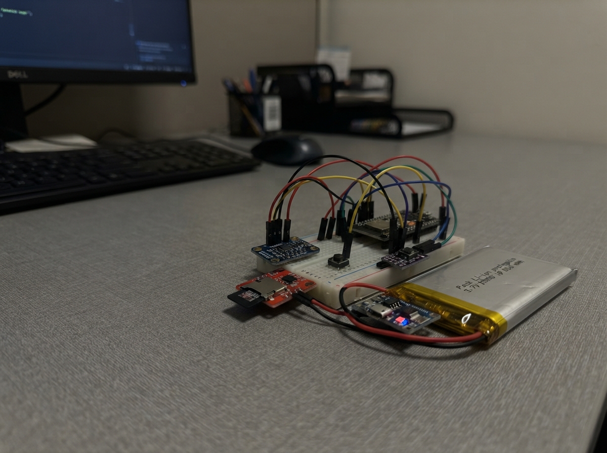
This wireless crane vibration monitor uses an ESP32 microcontroller paired with a 6-axis accelerometer to continuously track vibration patterns on industrial crane equipment. The device logs acceleration data to an onboard microSD card with precise timestamps from the RTC module, then enters low-power sleep mode to maximize battery life. A 10,000 mAh protected Li-ion cell powers the entire system, charged via the TP4056 module and regulated by a 3.3V buck-boost converter.
This guide provides a complete wiring diagram, parts list, and step-by-step assembly instructions for mounting the sensor to your crane structure. You'll also receive the complete firmware with I2C communication routines for the accelerometer and RTC, SD card logging functionality, and a web interface for downloading recorded vibration data. A push button allows switching between monitoring and download modes, making it easy to retrieve historical vibration logs for predictive maintenance analysis.
Wiring diagram

Gather all the parts
Assemble it in 6 steps
1. Prepara una caja firme y seca
Usa una caja cerrada con prensaestopas para que el polvo y el movimiento del puente grúa no tiren de los cables. Fija la caja a una zona rígida de la estructura, no a una cubierta fina que pueda añadir su propia vibración.
- Marca en la caja las direcciones X, Y y Z del MPU6050 antes de cerrarla; así los ejes del archivo CSV tendrán significado al analizar los datos.
- No instales este prototipo donde pueda interferir con el movimiento, el freno, los cables de carga ni los sistemas de seguridad del puente grúa.
2. Conecta la batería, cargador y regulador
Conecta BAT+ de la batería al terminal B+ del TP4056 y BAT− al B−. Conecta OUT+ del TP4056 a VIN del regulador de 3,3 V; conecta OUT− del cargador y GND del regulador al mismo GND. La salida VOUT del regulador es el cable de 3,3 V que alimenta el ESP32 y los módulos.
- Antes de conectar el ESP32, mide la salida del regulador: debe ser 3,3 V, no 5 V.
- No conectes la batería al revés: una batería invertida puede dañar el cargador, el regulador y el ESP32.
- Carga el pack únicamente por IN+ e IN− del TP4056 con una fuente USB de 5 V; no alimentes el TP4056 desde la red eléctrica directamente.
3. Alimenta el ESP32 y el sensor
Lleva VOUT de 3,3 V del regulador al pin 3V3 del ESP32, al VIN del MPU6050, al VCC del PCF85063 y al VCC de la microSD. Une todos los pines GND: regulador, ESP32, MPU6050, PCF85063 y microSD. Conecta SDA del MPU6050 y SDA del PCF85063 a GPIO21; conecta sus SCL a GPIO22.
- 3V3 → 3V3/VIN (alimentación); GND → GND (retorno); SDA → GPIO21 (datos); SCL → GPIO22 (reloj). Mantén estos cables cortos y juntos.
- No alimentes los módulos de datos a 5 V: el ESP32 trabaja a 3,3 V y 5 V en sus pines de datos puede dañarlo.
- Asegúrate de que el MPU6050 y el PCF85063 tengan direcciones distintas; estos módulos se comparten los mismos dos cables de datos.
4. Conecta la tarjeta de memoria y el botón
En el módulo microSD conecta MISO a GPIO19, MOSI a GPIO23, SCK a GPIO18 y CS a GPIO4. Coloca una pata del pulsador a GPIO27 y la otra a GND. Inserta una tarjeta microSD industrial formateada en FAT32.
- MISO → GPIO19 (datos hacia el ESP32), MOSI → GPIO23 (datos hacia la tarjeta), SCK → GPIO18 (ritmo de datos), CS → GPIO4 (selecciona la tarjeta), un lado del botón → GPIO27 y el otro → GND (modo descarga).
- No extraigas la microSD mientras el registrador está alimentado: podrías perder o corromper registros.
- GPIO4 se usa como selección de la microSD; revisa cuidadosamente que no esté tocando otro cable.
5. Sujeta el sensor al puente grúa
Atornilla o pega el MPU6050 sobre una superficie metálica rígida y limpia del puente grúa, usando fijación mecánica firme. No lo dejes colgando de sus cables. Pon el ESP32, la batería y la tarjeta dentro de la caja y deja accesible el pulsador.
- Una fijación floja mide el traqueteo de la caja, no la vibración real de la estructura. Anota en qué parte del puente grúa queda instalado.
- La batería debe quedar inmóvil dentro de la caja: si se desplaza, puede tirar de cables o falsear la vibración medida.
6. Ajusta la fecha y descarga el registro
Para poner la fecha o descargar datos, mantén pulsado el botón mientras alimentas o despiertas el equipo. Conéctate desde un teléfono u ordenador a la red Wi‑Fi CraneVibe-Logger con contraseña vibracion2026. Abre 192.168.4.1 y descarga vibrations.csv. Para fijar la fecha, abre la dirección mostrada en la página principal con los valores de fecha y hora.
- El modo Wi‑Fi se cierra solo después de diez minutos para ahorrar batería. En funcionamiento normal, no pulses el botón al iniciar.
- No dejes la red Wi‑Fi abierta durante el mes de medida: consume mucha más batería que el modo de registro.
Review all connections
1. Connections between "imu_1" and "ESP32"
2. Connections between "rtc_1" and "ESP32"
3. Connections between "sd_1" and "ESP32"
4. Connections between "button_1" and "ESP32"
5. Connections between "battery_1" and "ESP32"
6. Connections between "charger_1" and "ESP32"
7. Connections between "regulator_1" and "ESP32"
Deploy the firmware
#include <Arduino.h>
#include <Wire.h>
#include <SPI.h>
#include <SD.h>
#include <WiFi.h>
#include <WebServer.h>
#include <esp_sleep.h>


struct DateTime {
  uint16_t year;
  uint8_t month, day, hour, minute, second;
};


// Forward declarations
uint8_t bcdToDec(uint8_t value);
uint8_t decToBcd(uint8_t value);
bool readRegisters(uint8_t address, uint8_t reg, uint8_t *data, size_t length);
bool writeRegister(uint8_t address, uint8_t reg, uint8_t value);
bool readRtc(DateTime &dt);
bool setRtc(const DateTime &dt);
String timestamp(const DateTime &dt);
bool initMpu();
bool readAcceleration(float &x, float &y, float &z);
bool appendMeasurement();
String statusJson();
void startDownloadMode();
void goToSleep();

constexpr uint8_t MPU_ADDR = 0x68;
constexpr uint8_t RTC_ADDR = 0x51;
constexpr int I2C_SDA_PIN = 21;
constexpr int I2C_SCL_PIN = 22;
constexpr int SD_CS_PIN = 4;
constexpr int SD_MOSI_PIN = 23;
constexpr int SD_MISO_PIN = 19;
constexpr int SD_SCK_PIN = 18;
constexpr int MODE_BUTTON_PIN = 27;
constexpr uint32_t SAMPLE_WINDOW_MS = 1000;
constexpr uint32_t SAMPLE_INTERVAL_MS = 5;
constexpr uint64_t SLEEP_US = 60ULL * 1000000ULL;
constexpr uint32_t DOWNLOAD_TIMEOUT_MS = 10UL * 60UL * 1000UL;

WebServer server(80);
uint32_t downloadStartedAt = 0;
bool sdReady = false;


uint8_t bcdToDec(uint8_t value) { return ((value >> 4) * 10) + (value & 0x0F); }
uint8_t decToBcd(uint8_t value) { return ((value / 10) << 4) | (value % 10); }

bool readRegisters(uint8_t address, uint8_t reg, uint8_t *data, size_t length) {
  Wire.beginTransmission(address);
  Wire.write(reg);
  if (Wire.endTransmission(false) != 0) return false;
  if (Wire.requestFrom((int)address, (int)length) != (int)length) return false;
  for (size_t i = 0; i < length; ++i) data[i] = Wire.read();
  return true;
}

bool writeRegister(uint8_t address, uint8_t reg, uint8_t value) {
  Wire.beginTransmission(address);
  Wire.write(reg);
  Wire.write(value);
  return Wire.endTransmission() == 0;
}

bool readRtc(DateTime &dt) {
  uint8_t raw[7];
  if (!readRegisters(RTC_ADDR, 0x04, raw, sizeof(raw))) return false;
  dt.second = bcdToDec(raw[0] & 0x7F);
  dt.minute = bcdToDec(raw[1] & 0x7F);
  dt.hour = bcdToDec(raw[2] & 0x3F);
  dt.day = bcdToDec(raw[3] & 0x3F);
  dt.month = bcdToDec(raw[5] & 0x1F);
  dt.year = 2000 + bcdToDec(raw[6]);
  return dt.month >= 1 && dt.month <= 12 && dt.day >= 1 && dt.day <= 31;
}

bool setRtc(const DateTime &dt) {
  if (dt.year < 2000 || dt.year > 2099 || dt.month < 1 || dt.month > 12 || dt.day < 1 || dt.day > 31 || dt.hour > 23 || dt.minute > 59 || dt.second > 59) return false;
  uint8_t raw[7] = {decToBcd(dt.second), decToBcd(dt.minute), decToBcd(dt.hour), decToBcd(dt.day), 1, decToBcd(dt.month), decToBcd(dt.year - 2000)};
  Wire.beginTransmission(RTC_ADDR);
  Wire.write(0x04);
  Wire.write(raw, sizeof(raw));
  return Wire.endTransmission() == 0;
}

String timestamp(const DateTime &dt) {
  char buffer[24];
  snprintf(buffer, sizeof(buffer), "%04u-%02u-%02uT%02u:%02u:%02u", dt.year, dt.month, dt.day, dt.hour, dt.minute, dt.second);
  return String(buffer);
}

bool initMpu() {
  if (!writeRegister(MPU_ADDR, 0x6B, 0x00)) return false; // wake
  delay(50);
  if (!writeRegister(MPU_ADDR, 0x1A, 0x03)) return false; // 44 Hz low-pass filter
  if (!writeRegister(MPU_ADDR, 0x1C, 0x10)) return false; // accelerometer +/-8 g
  return true;
}

bool readAcceleration(float &x, float &y, float &z) {
  uint8_t raw[6];
  if (!readRegisters(MPU_ADDR, 0x3B, raw, sizeof(raw))) return false;
  int16_t ax = (int16_t)((raw[0] << 8) | raw[1]);
  int16_t ay = (int16_t)((raw[2] << 8) | raw[3]);
  int16_t az = (int16_t)((raw[4] << 8) | raw[5]);
  x = ax / 4096.0f;
  y = ay / 4096.0f;
  z = az / 4096.0f;
  return true;
}

bool appendMeasurement() {
  if (!initMpu()) return false;
  float sumX = 0, sumY = 0, sumZ = 0;
  float sumSqX = 0, sumSqY = 0, sumSqZ = 0;
  float peakX = 0, peakY = 0, peakZ = 0;
  uint16_t count = 0;
  uint32_t started = millis();
  while (millis() - started < SAMPLE_WINDOW_MS) {
    float x, y, z;
    if (readAcceleration(x, y, z)) {
      sumX += x; sumY += y; sumZ += z;
      sumSqX += x * x; sumSqY += y * y; sumSqZ += z * z;
      ++count;
    }
    delay(SAMPLE_INTERVAL_MS);
  }
  if (count < 20) return false;
  float meanX = sumX / count, meanY = sumY / count, meanZ = sumZ / count;
  // RMS after removing the static acceleration; this represents vibration rather than mounting angle.
  float rmsX = sqrtf(fmaxf(0, sumSqX / count - meanX * meanX));
  float rmsY = sqrtf(fmaxf(0, sumSqY / count - meanY * meanY));
  float rmsZ = sqrtf(fmaxf(0, sumSqZ / count - meanZ * meanZ));
  // A second short pass captures the peak relative to the measured static value.
  started = millis();
  while (millis() - started < SAMPLE_WINDOW_MS) {
    float x, y, z;
    if (readAcceleration(x, y, z)) {
      peakX = fmaxf(peakX, fabsf(x - meanX));
      peakY = fmaxf(peakY, fabsf(y - meanY));
      peakZ = fmaxf(peakZ, fabsf(z - meanZ));
    }
    delay(SAMPLE_INTERVAL_MS);
  }
  DateTime dt{};
  String when = readRtc(dt) ? timestamp(dt) : "TIME_NOT_SET";
  // On the ESP32 SD library, FILE_WRITE appends when the file already exists.
  File file = SD.open("/vibrations.csv", FILE_WRITE);
  if (!file) return false;
  if (file.size() == 0) file.println("timestamp,samples,rms_x_g,rms_y_g,rms_z_g,peak_x_g,peak_y_g,peak_z_g");
  file.printf("%s,%u,%.5f,%.5f,%.5f,%.5f,%.5f,%.5f\n", when.c_str(), count, rmsX, rmsY, rmsZ, peakX, peakY, peakZ);
  file.close();
  return true;
}

String statusJson() {
  DateTime dt{};
  String now = readRtc(dt) ? timestamp(dt) : "TIME_NOT_SET";
  File file = SD.open("/vibrations.csv", FILE_READ);
  size_t bytes = file ? file.size() : 0;
  if (file) file.close();
  return String("{\"rtc\":\"") + now + "\",\"sd_ready\":" + (sdReady ? "true" : "false") + ",\"log_bytes\":" + String(bytes) + "}";
}

void startDownloadMode() {
  WiFi.mode(WIFI_AP);
  WiFi.softAP("CraneVibe-Logger", "vibracion2026");
  server.on("/", HTTP_GET, []() {
    const char *page = "<!doctype html><html><body><h2>Crane vibration logger</h2><p><a href='/download'>Download vibrations.csv</a></p><p><a href='/status'>Status</a></p><p>Set clock: /set-time?year=2026&month=1&day=1&hour=12&minute=0&second=0</p></body></html>";
    server.send(200, "text/html", page);
  });
  server.on("/status", HTTP_GET, []() { server.send(200, "application/json", statusJson()); });
  server.on("/download", HTTP_GET, []() {
    if (!sdReady || !SD.exists("/vibrations.csv")) { server.send(404, "text/plain", "No log file"); return; }
    File file = SD.open("/vibrations.csv", FILE_READ);
    server.sendHeader("Content-Disposition", "attachment; filename=vibrations.csv");
    server.setContentLength(file.size());
    server.send(200, "text/csv", "");
    char buffer[513];
    size_t count = 0;
    while (file.available()) {
      int nextByte = file.read();
      if (nextByte < 0) break;
      buffer[count++] = static_cast<char>(nextByte);
      if (count == sizeof(buffer) - 1) {
        buffer[count] = '\0';
        server.sendContent(buffer);
        count = 0;
      }
    }
    if (count > 0) {
      buffer[count] = '\0';
      server.sendContent(buffer);
    }
    file.close();
  });
  server.on("/set-time", HTTP_GET, []() {
    if (!(server.hasArg("year") && server.hasArg("month") && server.hasArg("day") && server.hasArg("hour") && server.hasArg("minute") && server.hasArg("second"))) {
      server.send(400, "text/plain", "Missing date fields"); return;
    }
    DateTime dt{(uint16_t)server.arg("year").toInt(), (uint8_t)server.arg("month").toInt(), (uint8_t)server.arg("day").toInt(), (uint8_t)server.arg("hour").toInt(), (uint8_t)server.arg("minute").toInt(), (uint8_t)server.arg("second").toInt()};
    bool clockSet = setRtc(dt);
    server.send(clockSet ? 200 : 400, "text/plain", clockSet ? "Clock set" : "Invalid clock value");
  });
  server.begin();
  downloadStartedAt = millis();
}

void goToSleep() {
  Wire.end();
  // Holding the button low wakes the ESP32 directly into the download mode.
#if defined(ARDUINO_ARCH_ESP32)
  esp_sleep_enable_ext0_wakeup(static_cast<gpio_num_t>(MODE_BUTTON_PIN), 0);
#endif
  esp_sleep_enable_timer_wakeup(SLEEP_US);
  esp_deep_sleep_start();
}

void setup() {
  pinMode(MODE_BUTTON_PIN, INPUT_PULLUP);
  Wire.begin(I2C_SDA_PIN, I2C_SCL_PIN);
  SPI.begin(SD_SCK_PIN, SD_MISO_PIN, SD_MOSI_PIN, SD_CS_PIN);
  sdReady = SD.begin(SD_CS_PIN, SPI, 4000000);
  bool downloadMode = digitalRead(MODE_BUTTON_PIN) == LOW;
  if (downloadMode) {
    startDownloadMode();
    return;
  }
  if (sdReady) appendMeasurement();
  goToSleep();
}

void loop() {
  server.handleClient();
  if (millis() - downloadStartedAt > DOWNLOAD_TIMEOUT_MS) {
    WiFi.softAPdisconnect(true);
    goToSleep();
  }
}
Remix this project
Make it yours in one click
Open a full copy of this project in your own Schematik workspace — diagram, code, parts, and assembly steps included. Swap the sensor, add features, or redesign the whole thing with AI. The author's original stays untouched.
Related projects

Create A Complete Electrical Schematic Esp32 Sma
ESP32 · September 17, 2026Ayansh Agrawal
ESP32 Kare Ekran Projeleri
ESP32 · September 16, 2026Seref Ai
Component Qty --------------------------- ------
ESP32 · September 16, 2026Yathartha Chakrawal