On this page
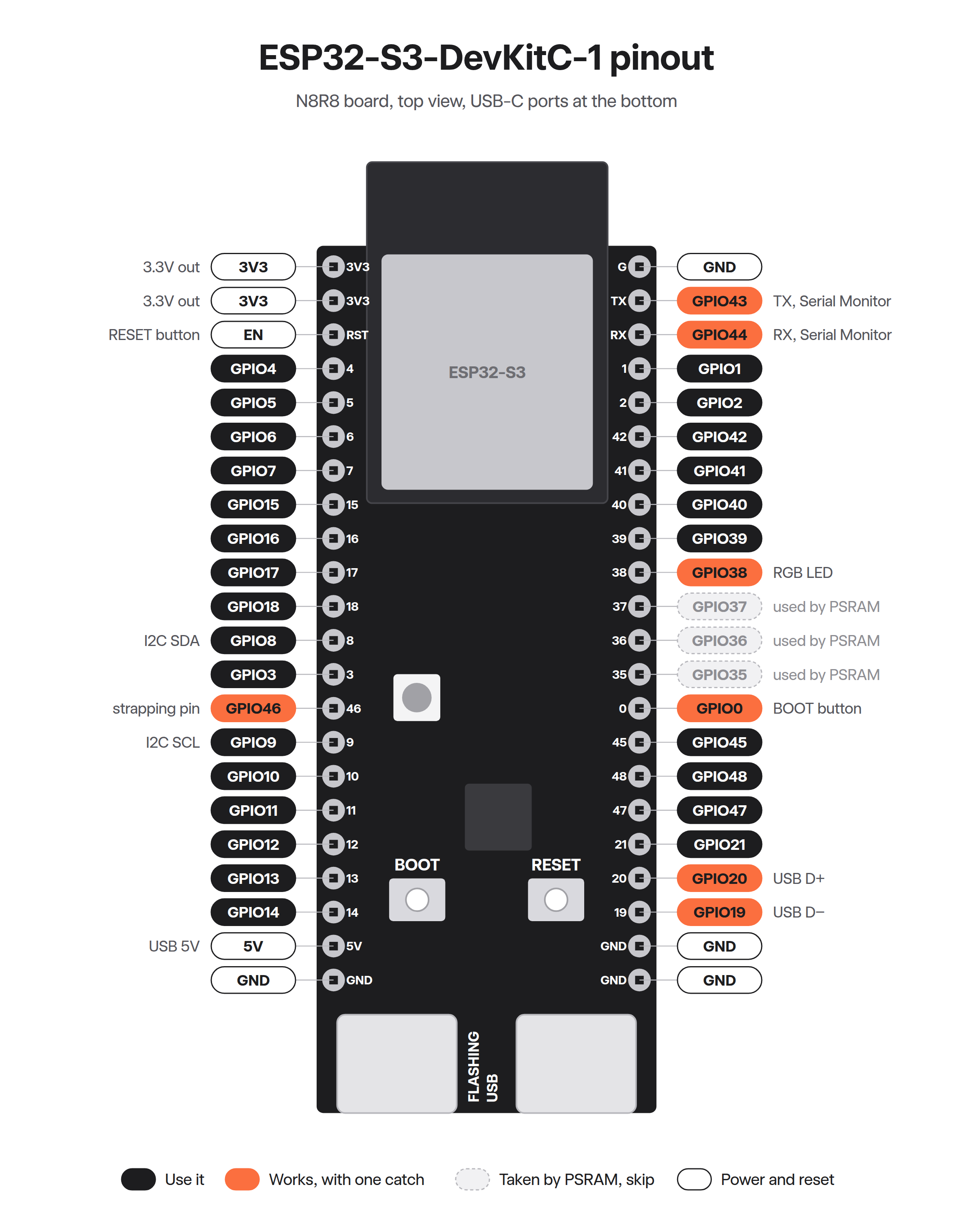
The ESP32-S3-DevKitC-1 has 44 pins, and 26 of them are general-purpose pins (GPIO) you can use right away for an LED, a button or a sensor. Another 7 work fine once you know their one catch. Three are taken by the board's own memory, so skip them.
This is the board in the Schematik Starter Kit, the ESP32-S3-DevKitC-1 N8R8: 8 MB of flash for your program and 8 MB of PSRAM, extra memory for things like screen images.
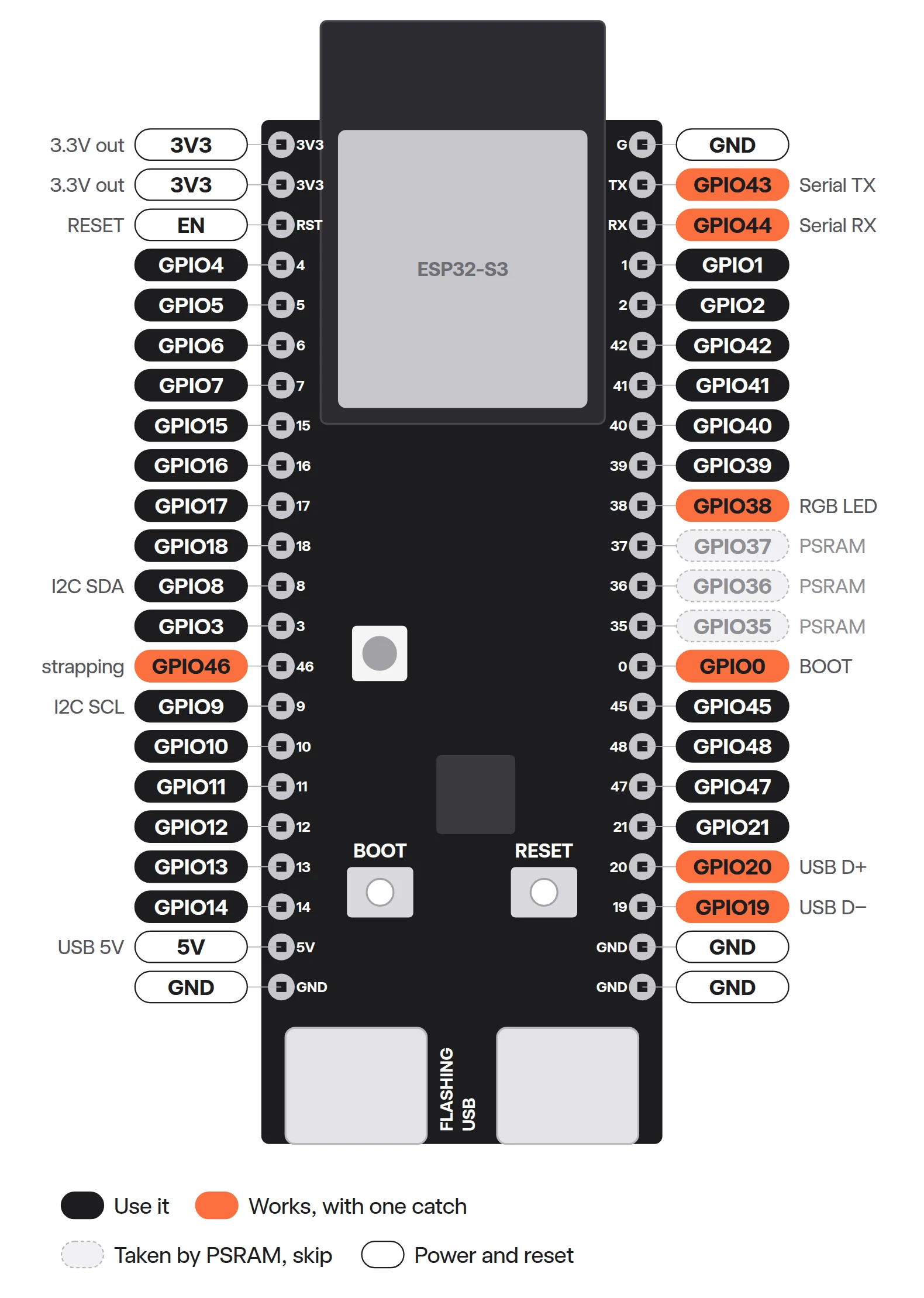
Want it next to your breadboard? Open the full-size pinout PNG and print it.
Do not connect 5V to a GPIO pin. Every GPIO on the ESP32-S3 expects at most 3.3V plus 0.3V. A 5V sensor output can damage the pin, so check what voltage a part sends back before you wire it.
Our picks for a first build
These are the pins the room monitor in the kit's example projects uses. Each one is a plain GPIO with no catch, so they're a good default for any first build.
| Job | Pin | Why this one |
|---|---|---|
| I2C SDA (screen data) | GPIO8 | Arduino's default SDA on the ESP32-S3 |
| I2C SCL (screen clock) | GPIO9 | Arduino's default SCL on the ESP32-S3 |
| Temperature sensor (DHT11) | GPIO4 | First GPIO on the left header |
| Motion sensor (PIR) | GPIO5 | Plain input |
| Light sensor | GPIO6 | Plain input |
| Pushbutton | GPIO7 | Plain input |
| LEDs | GPIO15, GPIO16, GPIO17 | Three in a row, each through a 220 Ω resistor |
All of them sit on the left header, so one side of the breadboard holds the whole build.
Which pins are I2C on the ESP32-S3?
Almost any free GPIO can be I2C on the ESP32-S3. The chip routes its I2C signals through a switchboard inside, so you pick the two pins in your code. SDA carries the data and SCL is the clock that keeps the board and the screen in step.
We use GPIO8 for SDA and GPIO9 for SCL. They're also the default I2C pins in Espressif's Arduino setup for this chip. On an original ESP32 the default is GPIO21 and GPIO22, which is why older tutorials show different numbers.
What the BOOT button does
The BOOT button connects GPIO0 to GND (ground) while you hold it. The board checks GPIO0 at the moment it starts up:
| GPIO0 when the board starts | What happens |
|---|---|
| High (BOOT not pressed) | Runs the program already on the board |
| Low (BOOT held down) | Waits for a new program over USB |
To put the board into download mode by hand, hold BOOT, press and release RESET, then let go of BOOT. You'll need this when the computer can't upload a new program on its own, for example when the program on the board crashes straight after it starts.
Most of the time you won't touch it. The board has two USB-C ports, and behind the one labeled FLASHING, two small transistors let the computer press BOOT and RESET for you. When you press Deploy in Schematik, the board switches to download mode on its own.
The RESET button restarts the ESP32-S3. It pulls the RST pin (also called EN) low, and your program starts again from the top.
Pins with one catch
These all work as GPIO. Each one has a job at startup or on the board that you need to know about first.
| Pin | The catch |
|---|---|
| GPIO0 | The BOOT button. If something holds it low when the board starts, the board waits for a new program instead of running yours. |
| GPIO46 | A strapping pin. Held high at startup together with BOOT, the board can't enter download mode. |
| GPIO43 (TX), GPIO44 (RX) | Wired to the FLASHING port's USB chip. They carry the Serial Monitor text, so using them for parts can garble uploads and messages. |
| GPIO19, GPIO20 | USB D− and D+ for the port labeled USB. Using them for parts turns that port off. |
| GPIO38 | Shares its line with the RGB LED on the board, so a part here and the LED are wired together. |
A strapping pin is a pin the chip reads once, at startup, to decide how to start. After that it's a normal GPIO. The catch only bites when a part holds the pin high or low while the board turns on. GPIO3 and GPIO45 are strapping pins too, but on this board the chip's factory settings ignore them, so they're plain GPIO.
Espressif's first version of this board (v1.0) drives the RGB LED from GPIO48, and Arduino's RGB_BUILTIN still points there. On the kit board, GPIO48 goes only to the header, so use GPIO38 for the LED.
The three pins to skip
GPIO35, GPIO36 and GPIO37 reach the header, but on the N8R8 board they're wired inside the module to the 8 MB of PSRAM. Using them can crash your program, so leave them empty.
GPIO22 to GPIO34 aren't on the headers at all. GPIO22 to GPIO25 don't exist on the ESP32-S3, and the rest connect to the flash and PSRAM inside the module.
Analog pins and Wi-Fi
To read a sensor that outputs a voltage, like a potentiometer, use GPIO1 to GPIO10. These are on ADC1, the first of the chip's two analog-to-digital converters (ADC), which turn a voltage into a number.
GPIO11 to GPIO20 are on ADC2, which shares hardware with Wi-Fi. While Wi-Fi is on, an analog reading on those pins can fail, so keep sensors on ADC1. Digital parts like buttons and LEDs work on them either way.
Full ESP32-S3-DevKitC-1 pin table
Pin numbers count from the end with the module. The left header is J1 and the right header is J3, the names used in the board's schematic.
Left header (J1)
| No. | Label | Pin | Use it? | Notes |
|---|---|---|---|---|
| 1 | 3V3 | 3.3V | Power | 3.3V out for sensors |
| 2 | 3V3 | 3.3V | Power | 3.3V out for sensors |
| 3 | RST | EN | Reset | RESET button pulls it low |
| 4 | 4 | GPIO4 | Yes | ADC1, room monitor DHT11 |
| 5 | 5 | GPIO5 | Yes | ADC1, room monitor PIR |
| 6 | 6 | GPIO6 | Yes | ADC1, room monitor light sensor |
| 7 | 7 | GPIO7 | Yes | ADC1, room monitor button |
| 8 | 15 | GPIO15 | Yes | ADC2, room monitor green LED |
| 9 | 16 | GPIO16 | Yes | ADC2, room monitor yellow LED |
| 10 | 17 | GPIO17 | Yes | ADC2, room monitor red LED |
| 11 | 18 | GPIO18 | Yes | ADC2 |
| 12 | 8 | GPIO8 | Yes | ADC1, I2C SDA |
| 13 | 3 | GPIO3 | Yes | ADC1, strapping pin, ignored on this board |
| 14 | 46 | GPIO46 | One catch | Strapping pin |
| 15 | 9 | GPIO9 | Yes | ADC1, I2C SCL |
| 16 | 10 | GPIO10 | Yes | ADC1 |
| 17 | 11 | GPIO11 | Yes | ADC2 |
| 18 | 12 | GPIO12 | Yes | ADC2 |
| 19 | 13 | GPIO13 | Yes | ADC2 |
| 20 | 14 | GPIO14 | Yes | ADC2 |
| 21 | 5V | 5V | Power | 5V from USB |
| 22 | GND | GND | Ground |
Right header (J3)
| No. | Label | Pin | Use it? | Notes |
|---|---|---|---|---|
| 1 | G | GND | Ground | |
| 2 | TX | GPIO43 | One catch | Serial Monitor TX |
| 3 | RX | GPIO44 | One catch | Serial Monitor RX |
| 4 | 1 | GPIO1 | Yes | ADC1 |
| 5 | 2 | GPIO2 | Yes | ADC1 |
| 6 | 42 | GPIO42 | Yes | |
| 7 | 41 | GPIO41 | Yes | |
| 8 | 40 | GPIO40 | Yes | |
| 9 | 39 | GPIO39 | Yes | |
| 10 | 38 | GPIO38 | One catch | RGB LED |
| 11 | 37 | GPIO37 | Skip | Used by PSRAM |
| 12 | 36 | GPIO36 | Skip | Used by PSRAM |
| 13 | 35 | GPIO35 | Skip | Used by PSRAM |
| 14 | 0 | GPIO0 | One catch | BOOT button |
| 15 | 45 | GPIO45 | Yes | Strapping pin, ignored on this board |
| 16 | 48 | GPIO48 | Yes | |
| 17 | 47 | GPIO47 | Yes | |
| 18 | 21 | GPIO21 | Yes | |
| 19 | 20 | GPIO20 | One catch | USB D+ |
| 20 | 19 | GPIO19 | One catch | USB D− |
| 21 | GND | GND | Ground | |
| 22 | GND | GND | Ground |
Try it on your desk
Wire a 0.96" SSD1306 OLED screen to 3V3, GND, GPIO8 and GPIO9, and you have the start of the tiny OLED desk command center. Add a DHT11 on GPIO4 and the screen can show your room's temperature too. For how breadboard rows and power rails work, the beginner ESP32 hardware guide walks through it. Which pin would you pick for a buzzer?
Keep building from here
Jump into a step-by-step build, or open Schematik and turn your own idea into code, wiring, and assembly instructions.
Related posts
New to Hardware? A Beginner ESP32 Guide for Your First Build
A beginner ESP32 hardware guide: what to buy first, how breadboards work, what pin labels mean, and what to check before powering your first build.
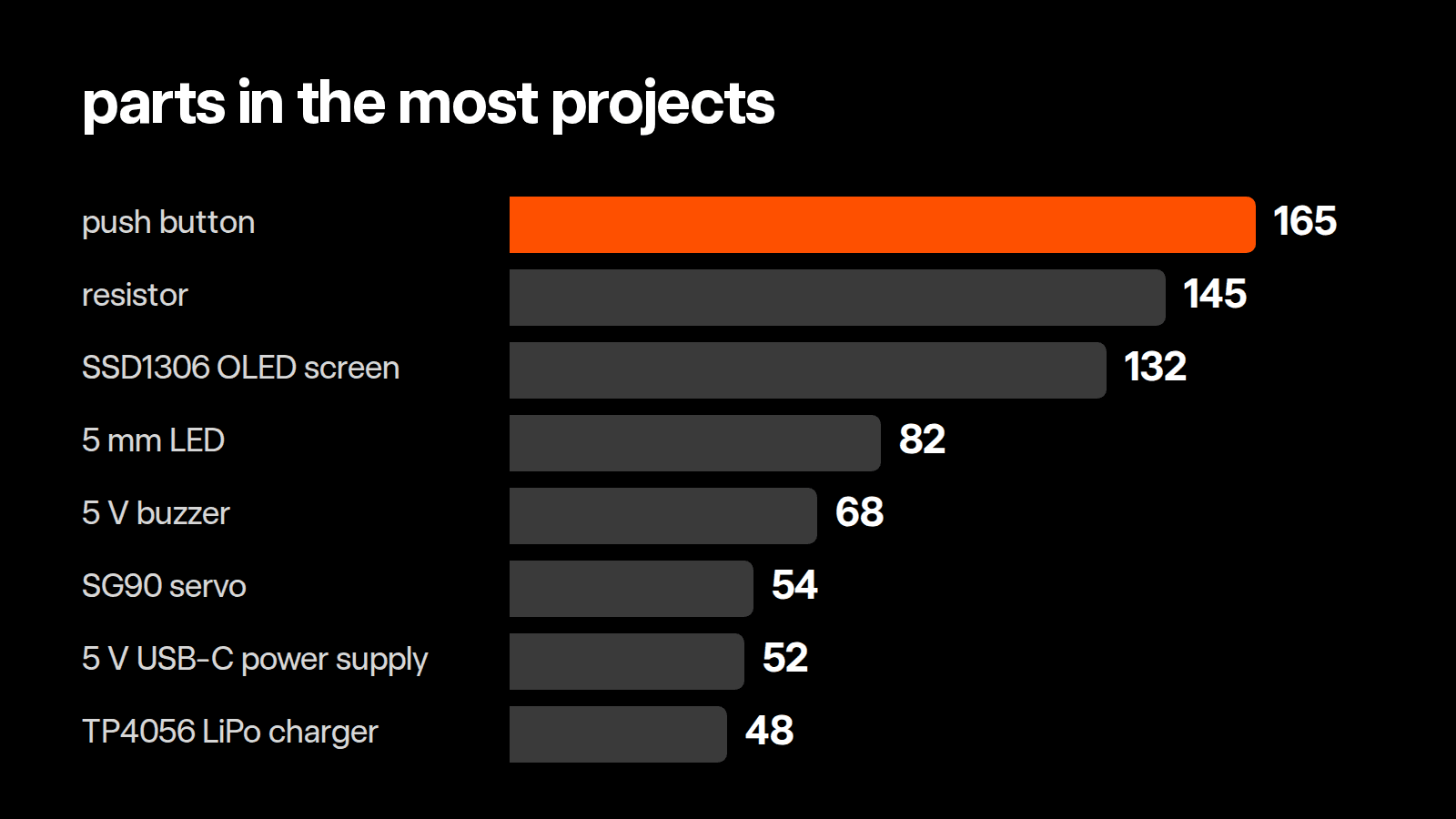
Most-used parts in Schematik projects
We counted the parts in all 902 published Schematik projects. A push button beat every screen and sensor, and one project in six adds no parts at all.
Related builds
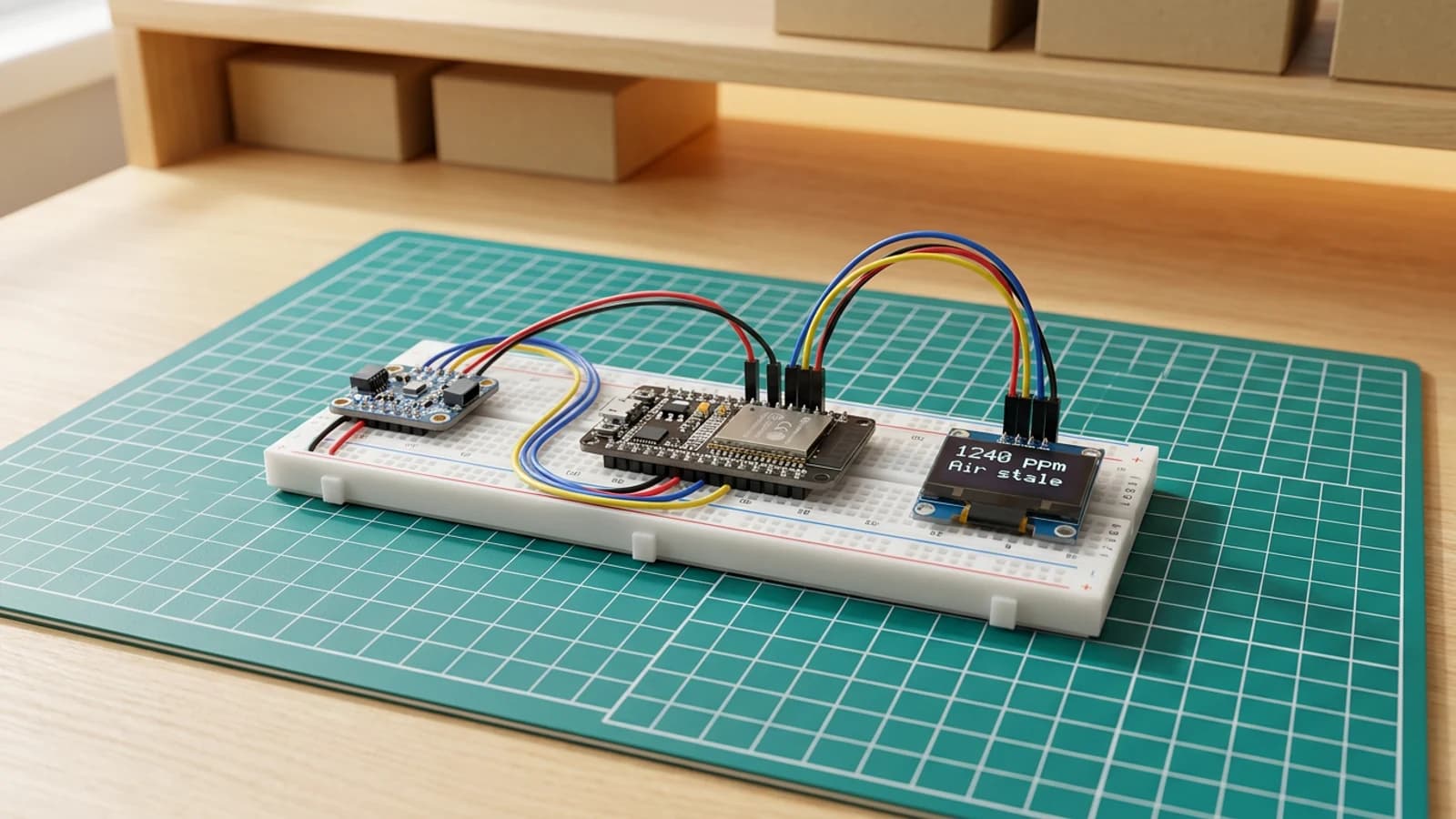
How to Build a CO2 Room Monitor with ESP32
Build an ESP32 CO2 monitor with an Adafruit SCD41 sensor, SSD1306 OLED, shared I2C wiring, warning thresholds, and live temperature and humidity readings.

How to Build a Tiny OLED Desk Command Centre
Build an ESP32 OLED desk display with Wi-Fi, weather, time, local IP printing, and a browser page for sending messages to the screen.

How to Build an ESP32 Weather Station with Clothing Advice
Build an ESP32 weather station that fetches Amsterdam forecast data over Wi-Fi and shows simple clothing advice on a Waveshare 1.83-inch LCD. Includes complete code and wiring guide.