
On this page
- The short version
- Who this guide is for
- Best first ESP32 setup for beginners
- Easiest first ESP32 setup
- What to buy first
- What do ESP32 pin labels mean?
- What's a breadboard?
- Pre-power checklist for beginner hardware
- Most common hardware issues
- Great first hardware projects
- Beginner hardware FAQ
- A simple first Schematik session
Beginner hardware is mostly about reading labels, sharing ground, lining up breadboard rows, checking connector direction, and using parts that match the guide you are following.
A guide might say "connect SDA and SCL" before explaining that those are the two I2C signal wires. It might say "use the analogue output" before explaining that a sensor module can have both AO and DO pins.
So this guide starts with the desk in front of you: the board, the breadboard, the labels, the wires, and the first checks to make before powering anything.
Most beginner hardware issues come from labels, orientation, voltage, ground, and connectors.
The short version
For a first hardware build, start with an ESP32 board, a small screen, a breadboard, jumper wires, a USB data cable, and one simple input such as a button or light sensor.
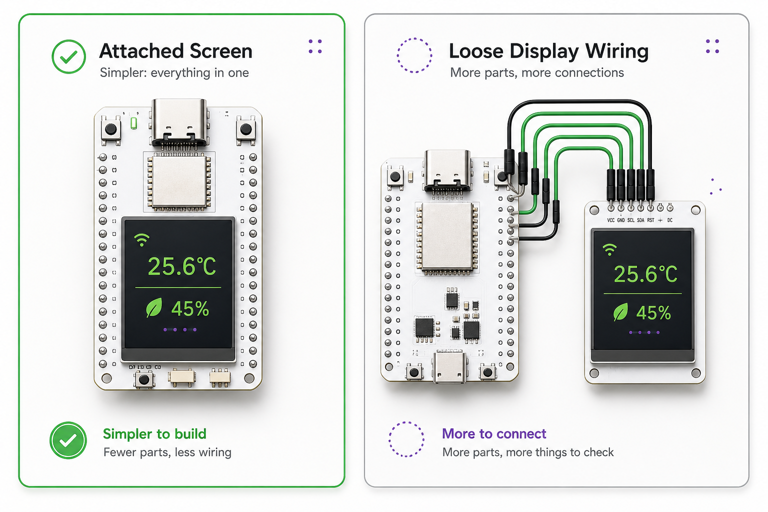
The easiest first setup is an ESP32 board with the screen already attached. It removes several wires from the build, so you can learn labels, power, ground, and code upload before debugging loose display wiring.
Who this guide is for
This guide is for people who can follow software instructions but are new to physical hardware: ESP32 boards, breadboards, jumper wires, displays, and sensors.
It is not an electronics theory guide. It is a practical first-build guide for getting one small thing working without frying parts or guessing where every wire goes.
Best first ESP32 setup for beginners
Do not start with a robot arm, a battery system, three sensors, an enclosure, and a long feature list.
Start with one board and one output you can see.
For most beginners, that means an ESP32 and a screen:
- an ESP32 board with a built-in display
- a normal ESP32 plus a small OLED
- a beginner-friendly ESP32 touch LCD board
A blinking LED is still a useful first project. It proves the board can run code. A screen gives you more feedback: text, a number, a menu, a sensor value, Wi-Fi status, or a simple "ready" message.
If you can, start with the screen already attached. The Waveshare ESP32-C6 1.69 inch touch LCD board and the non-touch Waveshare ESP32-C6 1.69 inch LCD board are good examples because the display hardware is already on the PCB. You still need the right firmware settings, but you remove several loose wires from the first build.
A normal ESP32 with a small OLED display is also a good start. It adds a little wiring, but the connections are still simple enough to inspect.
Good catalogue examples to look at:
- Waveshare ESP32-C6 1.69 inch touch LCD board, an ESP32-C6 board with the touch display already attached
- Waveshare ESP32-C6 1.69 inch LCD board, a non-touch screen board with fewer display wires to get wrong
- ESP32-C6-DevKitC-1, a sensible ESP32-C6 development board when you want separate modules
- Seeed WT32 4.3 inch ESP32-S3 display board, a bigger screen board with more of the display hardware already on the PCB
Easiest first ESP32 setup
-
easiest: ESP32 board with built-in screen
- fewer loose wires
- good for clocks, dashboards, menus, weather, and status displays
-
still beginner-friendly: ESP32 plus small OLED
- adds wiring practice
- usually uses
GND,3V3,SDA, andSCL
-
harder: ESP32 plus multiple sensors, motors, batteries, or LED strips
- more power issues
- more wiring mistakes
- harder to debug when nothing works
Once you have picked the shape of the first build, keep the shopping list boring. Boring is good here. It means fewer mystery failures when you plug the board in.
What to buy first
Buy less than you think. A good first ESP32 hardware starter kit is:
- ESP32 board, ideally one with a built-in screen
- USB data cable
- breadboard
- male-to-male jumper wires
- one button
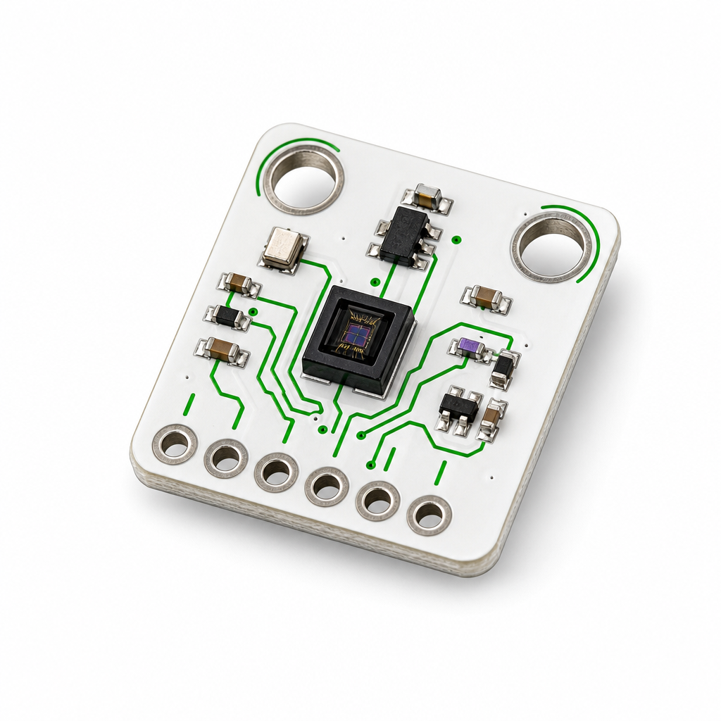
- one simple sensor, such as a light or temperature sensor
- optional small OLED display if your board does not have a screen
Avoid motors, batteries, LED strips, servos, pumps, and bench power supplies until the first simple build works.
For a first session, a sensible kit looks like this:
- an ESP32 dev board, or an ESP32 board with a screen already attached
- a USB cable that can transfer data, rather than a charge-only cable
- a breadboard
- male-to-male jumper wires for breadboard work
- female-to-female or female-to-male jumper wires if your modules have pins sticking out
- one simple input, like a button, light sensor, temperature sensor, or distance sensor
That is enough.
Skip the 37-in-1 sensor kit for now. Skip the bench power supply. Skip motors, servos, LED strips, batteries, and anything with enough current to make debugging smell funny. We know it is tempting to order more. The problem is that a full drawer of parts gives you more ways to build the wrong thing before you have one small thing working.
When the mail arrives with your sweet new hardware, open Schematik and go from parts to working hardware you can customise to your liking. If you are new to building, or you just want to do everything in one place, give it a shot and let us know how you get on in our Discord.
What do ESP32 pin labels mean?
The first useful hardware skill is reading the labels printed on the board and modules.
A pin label is a short name for what that metal pin is meant to do. Some labels describe power. Some describe signals. Some describe a feature of the microcontroller.
Common labels:
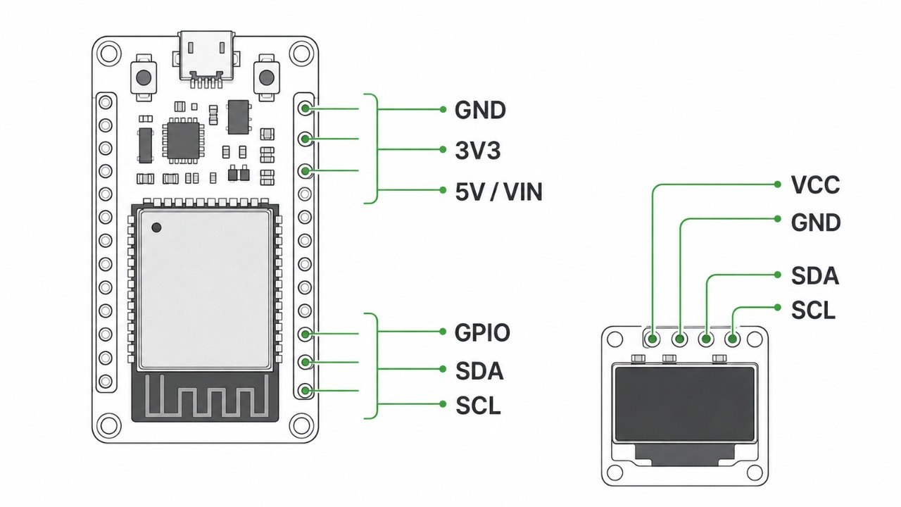
GNDmeans ground. Think of ground as the shared return path for the circuit. If two parts need to talk to each other, they usually need theirGNDpins connected together so they agree on what "low" means.3V3means 3.3 volts. Many ESP32 boards run their signal pins at 3.3 V.5VorVINusually means a power input or USB-derived power rail. It does not automatically mean every pin on the board can handle 5 V.GPIO25means general purpose input/output pin 25. It is a controllable ESP32 signal pin.SDAandSCLare the usual I2C data and clock lines. Many small sensors and OLED displays use I2C.MOSI,MISO,SCK,CS,DC, andRSToften appear on SPI displays.AOmeans analogue output. Use it when you want a changing sensor value, such as more light or less light.DOmeans digital output. It usually gives a simple on/off result based on a threshold set on the module.VCCis the module's power input. Check whether the module wants 3.3 V, 5 V, or accepts both.
Your exact board may move labels around, so match any diagram to the board on your desk before wiring. A module can be more forgiving than the chip mounted on it. Some breakouts include a regulator or level shifting. Others expose the chip pins directly. Check the module documentation when power labels are unclear.
For ESP32 projects, use this safe starting rule: power modules from the voltage they specify, and treat ESP32 GPIO signal pins as 3.3 V inputs unless the exact board documentation says otherwise.
What's a breadboard?
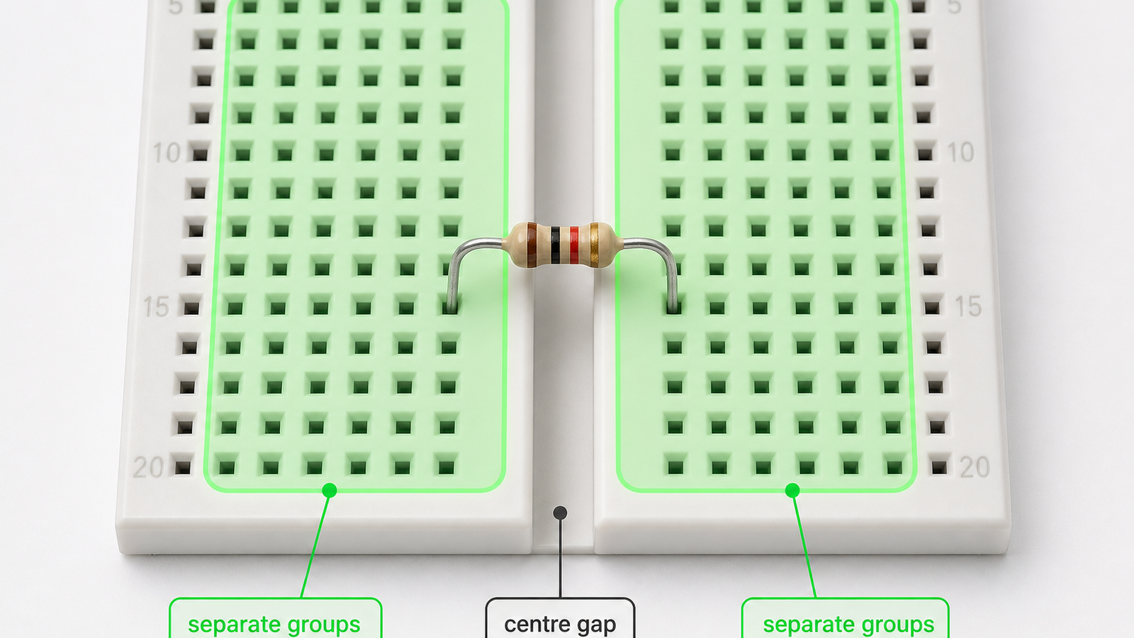
A breadboard lets you connect parts without soldering. Under the plastic are metal clips that join groups of holes together.
On the main area, holes in the same numbered row are connected on each side of the centre gap. A row is one horizontal numbered line of holes. Connected means those holes behave as if a short hidden wire joins them underneath.
The centre gap separates the two sides. A wire or component leg on the left side of the gap is not connected to a hole on the right side unless something bridges the gap.
Roughly:
A B C D E    gap    F G H I J
same row            same row
The side rails are different. They usually run vertically and are used for power, often marked + and -. Some breadboards split those rails halfway down, so the top half and bottom half may not be connected unless you bridge them with a jumper wire.
When someone says:
button signal -> GPIO25
they do not always mean the button leg must touch the ESP32 pin directly. You can use the breadboard row as a connection point:
ESP32 GPIO25 -> empty breadboard row
button leg   -> same breadboard row
button other -> GND rail
The ESP32 pin and the button leg are electrically connected because they share the same row.
This is also a common source of mistakes. Two legs in different holes can still be connected if they are in the same row. For a two-leg part such as a resistor, button, LED, or buzzer, put the legs in different connected groups. If a part needs to cross the middle of the breadboard, place it across the centre gap.
Pre-power checklist for beginner hardware
Before plugging in USB or switching on power, take a minute to check the physical build.
- Check
GNDis connected between the ESP32 and any module that sends or receives a signal. - Check power goes to the correct pin:
3V3,5V,VIN, orVCC. This depends on what you are building and what each module expects. - Check signal wires go to signal pins, not power rails.
- Check LEDs, buzzers, diodes, batteries, and electrolytic capacitors are the right way round.
- Check buttons and resistors are not placed with both legs in the same connected breadboard row.
- Check I2C modules have
SDAtoSDAandSCLtoSCL. - Check SPI displays match the exact pins used in the code.
- Check loose jumper wires are fully seated.
- Check metal parts are not touching in a way the diagram does not show.
For a first build, power from USB and keep motors, servos, pumps, heaters, batteries, and LED strips out of the circuit until the simple version works. If you tell Schematik Agent what you are building, it can turn these checks into project-specific wiring, power, pin, and install steps instead of leaving you to guess from a generic list.
Most common hardware issues
When a beginner build does not respond, start with the checks that are easiest to verify.
The code may upload successfully while the screen is still black, the sensor value is wrong, or a second module does not appear. That does not mean the project is broken. It usually means one physical assumption needs checking.
The board is missing over USB
Try another cable first. Some USB cables only charge.
If another cable does not help, check:
- the board appears as a serial device
- the browser supports Web Serial if you are flashing from the browser
- the board needs a USB-to-serial driver
- the board needs you to hold
BOOTwhile flashing - the selected board variant matches the board on your desk
The screen stays black
A black screen can mean too many things:
- no power
- no shared ground
- wrong display driver
- wrong I2C address
- wrong SPI pins
- reset pin wrong
- backlight pin missing
- ribbon cable backwards
- the code is running, but drawing off-screen or using the wrong rotation
Check power and backlight first, connector orientation second, then pins, address, driver, and rotation settings.
The sensor reads nonsense
Check the label and the output type.
For a simple light sensor module, for example:
VCC -> 3V3
GND -> GND
AO  -> analogue-capable ESP32 pin
DO  -> leave unconnected unless you want on/off threshold behaviour
If the guide describes a bare LDR but your part is a small sensor module, follow the module wiring. A bare component circuit and a breakout module can need different supporting parts.
The board resets when something turns on
Suspect power.
Motors, speakers, pumps, servos, thermal printers, and long LED strips should not be powered casually from a dev board pin. Use a suitable external supply, and if that powered thing talks to the ESP32, it normally still needs a shared ground.
Great first hardware projects
ESP32 with a screen
For a first project, make something you can glance at: a clock, status page, sensor value, tiny menu, or one useful value from an API such as weather, calendar status, or a build result.
Try:
- Build an ESP32-C6 touch LCD gadget
- Build a tiny OLED desk command centre
- Build a touchscreen chess game on an ESP32 display board
An ESP32 board with the screen and touch hardware already on the PCB is a good beginner shape. There is less loose wiring to get wrong.
Weather station
A weather station is a good first connected build because the behaviour is obvious. It reads a value, formats it, and shows the result.
You can use physical sensors, or fetch forecast data over Wi-Fi. For a first build, Wi-Fi plus Open-Meteo is a nice route because basic forecast calls work without an API key.
Try: Build an ESP32 weather station.
Desk light or focus timer
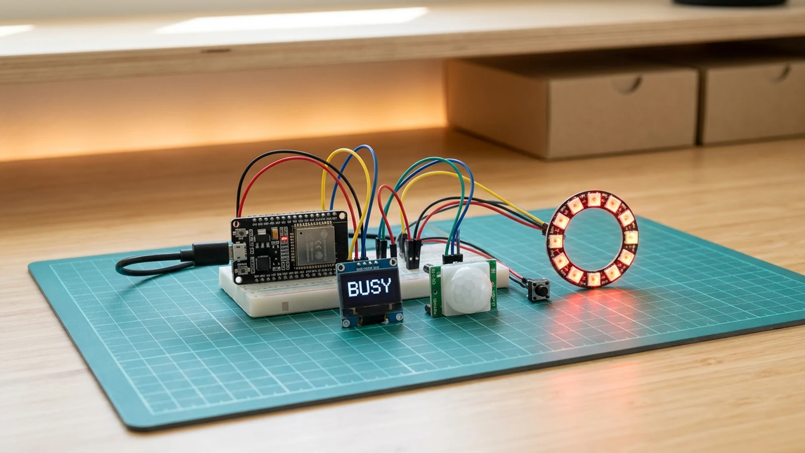
A presence light, focus timer, or small desk display teaches timing, buttons, LEDs, and state. It can also become something you actually leave on your desk.
Try:
Be careful with LED strips. One LED is easy. A strip can pull more current than a dev board should supply.
Room monitor
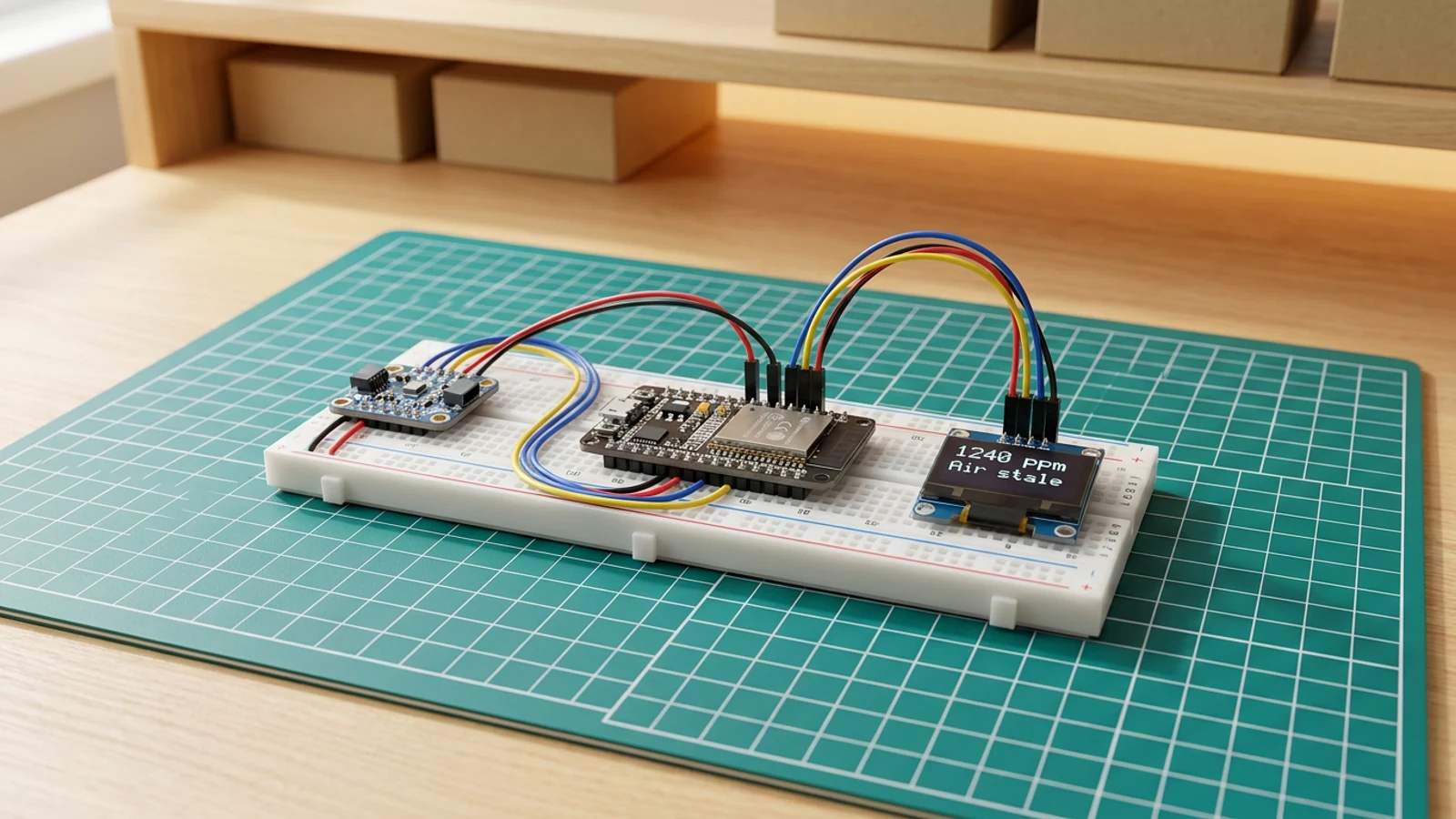
Temperature, humidity, CO2, air quality, light, and motion projects all teach the same useful pattern: read a value, smooth it or compare it against a threshold, display it, maybe trigger something.
Try:
Beginner hardware FAQ
What is the best first ESP32 project?
The best first ESP32 project is one board with one visible output, such as a small screen showing text, weather, a timer, or a sensor value. A screen gives clearer feedback than a blinking LED because you can see whether the code, power, and display setup are working.
Should beginners start with an ESP32 and a screen?
Yes, if the screen is already attached to the board. A built-in screen removes several loose wires from the first build. A separate OLED is still beginner-friendly, but it adds power, ground, SDA, and SCL wiring to check.
What usually goes wrong in a first hardware build?
The common problems are wrong pin labels, missing shared ground, charge-only USB cables, reversed connectors, wrong voltage, loose jumper wires, and breadboard rows misunderstood as separate holes.
Can I power sensors from an ESP32?
Small sensors often work from the ESP32 board's 3V3 pin, but check the module documentation. Do not power motors, servos, pumps, heaters, speakers, thermal printers, or long LED strips from an ESP32 GPIO pin.
Do all ESP32 boards have the same pinout?
No. ESP32 boards can move labels around. Match the guide to the exact board on your desk, and check the board documentation before wiring power or signal pins.
A simple first Schematik session
For a first Schematik session, use this order:
- Pick an ESP32 board with a built-in screen, or an ESP32 plus a small OLED.
- Follow one guide exactly once.
- Build the guide version before customising anything.
- Change one small thing: the text, colour, update interval, displayed value, or threshold.
- Upload again.
- Only then add a sensor, button, API, enclosure idea, battery plan, or more complex interface.
Changing five things at once makes the build harder to inspect because you cannot tell which change caused the failure.
Schematik helps when the generic guide stops being enough. Describe the build you want, the board you have, and the module labels in front of you. Schematik can turn that into a project-specific parts list, wiring plan, firmware, install steps, and deploy flow.
You still check the board on your desk, but you are not jumping between disconnected notes, diagrams, and code snippets.
Open Schematik, describe the small thing you want to build, and keep the first version small enough to finish in one sitting.
Keep building from here
Jump into a step-by-step build, or open Schematik and turn your own idea into code, wiring, and assembly instructions.
Related posts

I Built a Touchscreen Chess Game With Zero Hardware Skills
For week three in the Schematik workshop, I turned a viral idea for a distraction-free chess device into a working touchscreen chess game on an ESP32 Cheap Yellow Display.

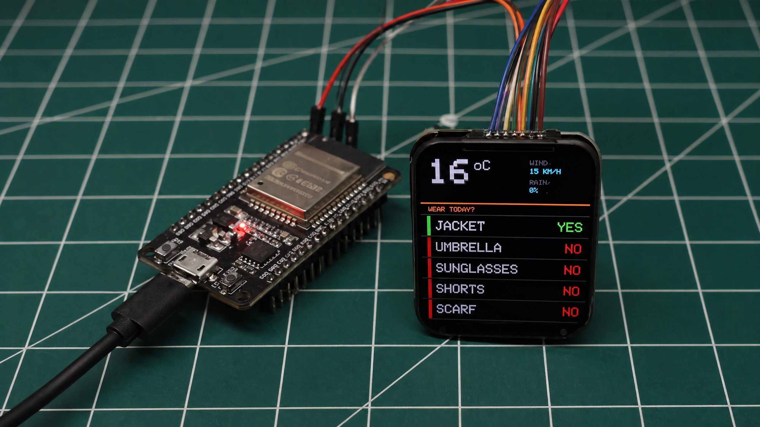
I Built an ESP32 Weather Station That Tells Me What to Wear
For week two in the Schematik workshop, I built a tiny ESP32 weather station that checks the forecast and tells me whether to take a jacket, umbrella, sunglasses, shorts, or scarf.
Related builds

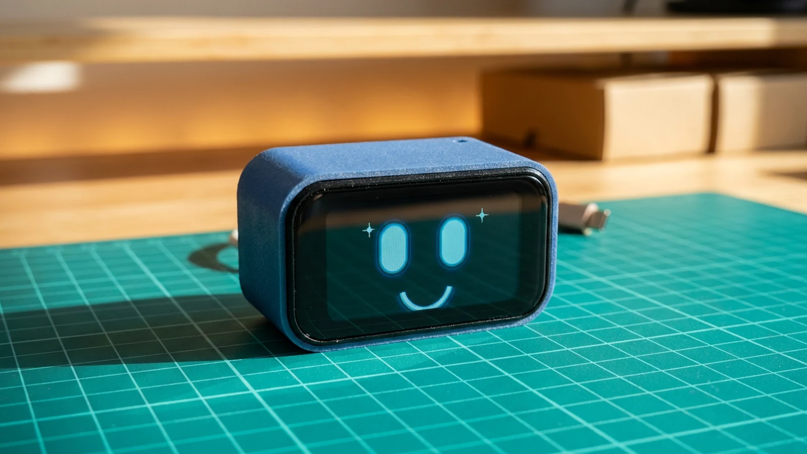
How to Build a Tiny ESP DeskBuddy with ESP32-C6
Build a small ESP32-C6 touch LCD DeskBuddy with a monochrome animated face, swipeable dashboard pages, Wi-Fi data cards, and printed enclosure.

How to Build a Tiny OLED Desk Command Centre
Build an ESP32 OLED desk display with Wi-Fi, weather, time, local IP printing, and a browser page for sending messages to the screen.

How to Build an ESP32 Weather Station with Clothing Advice
Build an ESP32 weather station that fetches Amsterdam forecast data over Wi-Fi and shows simple clothing advice on a Waveshare 1.83-inch LCD. Includes complete code and wiring guide.