On this page
You wire a button to your ESP32-S3, upload a sketch that prints "pressed", and the Serial Monitor starts printing it before you've touched anything. Wave your hand near the wires and it prints faster.
Nothing is broken. The pin is floating, and one resistor fixes it.
What is a floating pin?
A GPIO (general-purpose input/output) pin set as an input measures the voltage on its wire. It barely uses any current to do that: the ESP32-S3 datasheet lists 50nA at most, which is tiny.
That's great for battery life, and it means the pin has no opinion of its own. When the button is open, the pin is connected to nothing. Static from your hand or a signal in a nearby wire can nudge it up and down.
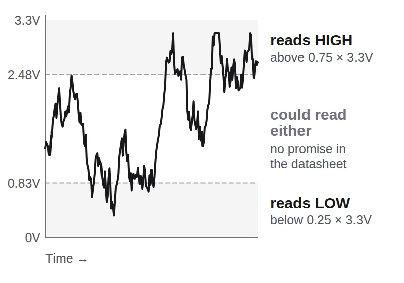
The ESP32-S3 datasheet only promises a HIGH reading above 0.75 × 3.3V (about 2.48V) and a LOW reading below 0.25 × 3.3V (about 0.83V). A floating pin wanders through all of it, so your sketch sees presses that never happened.
What does a pull-up resistor do?
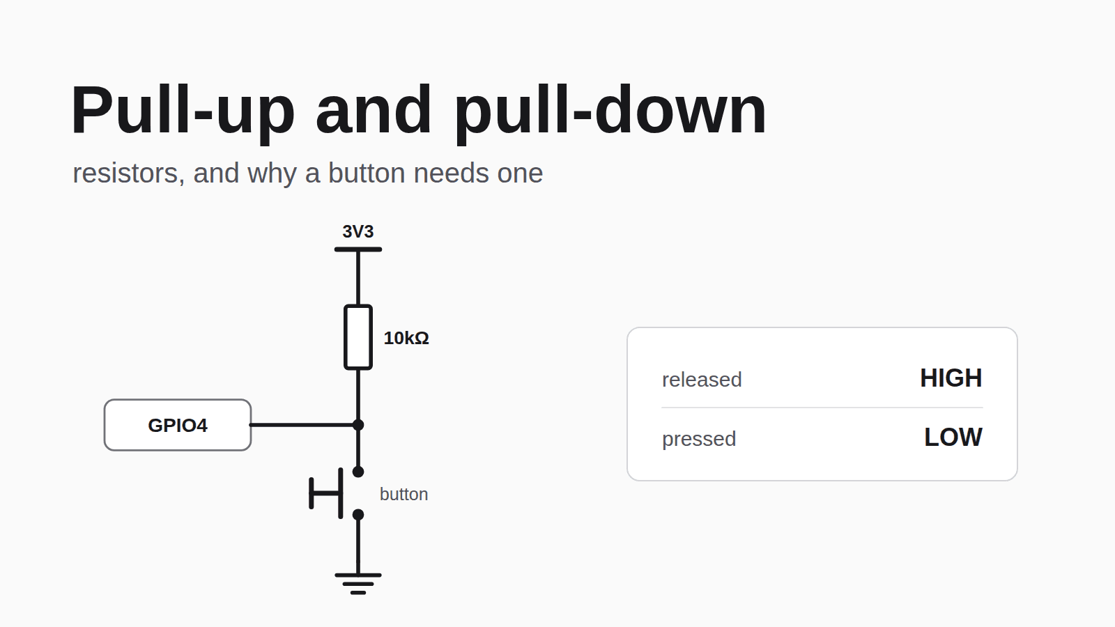
A pull-up resistor connects the pin to the board's 3V3 pin, its 3.3V supply, usually through 10kΩ. Then the button connects the pin to GND (ground), the 0V side of the circuit.
- Button released: the resistor gently pulls the pin up to 3.3V. It reads HIGH.
- Button pressed: the button connects the pin straight to GND, which wins easily over the resistor. It reads LOW.
The resistor also stops a short circuit. If you replaced it with a plain wire, pressing the button would connect 3V3 straight to GND. With 10kΩ in the way, only 0.33mA flows while you hold the button down (3.3V ÷ 10kΩ).
Pressed reads LOW, which can feel backwards at first. Your code checks for LOW to spot a press.
What does a pull-down resistor do?
A pull-down resistor flips the circuit. It connects the pin to GND through the resistor, and the button connects the pin to 3V3.
- Button released: the pin is pulled down to GND. It reads LOW.
- Button pressed: the pin connects to 3V3. It reads HIGH.
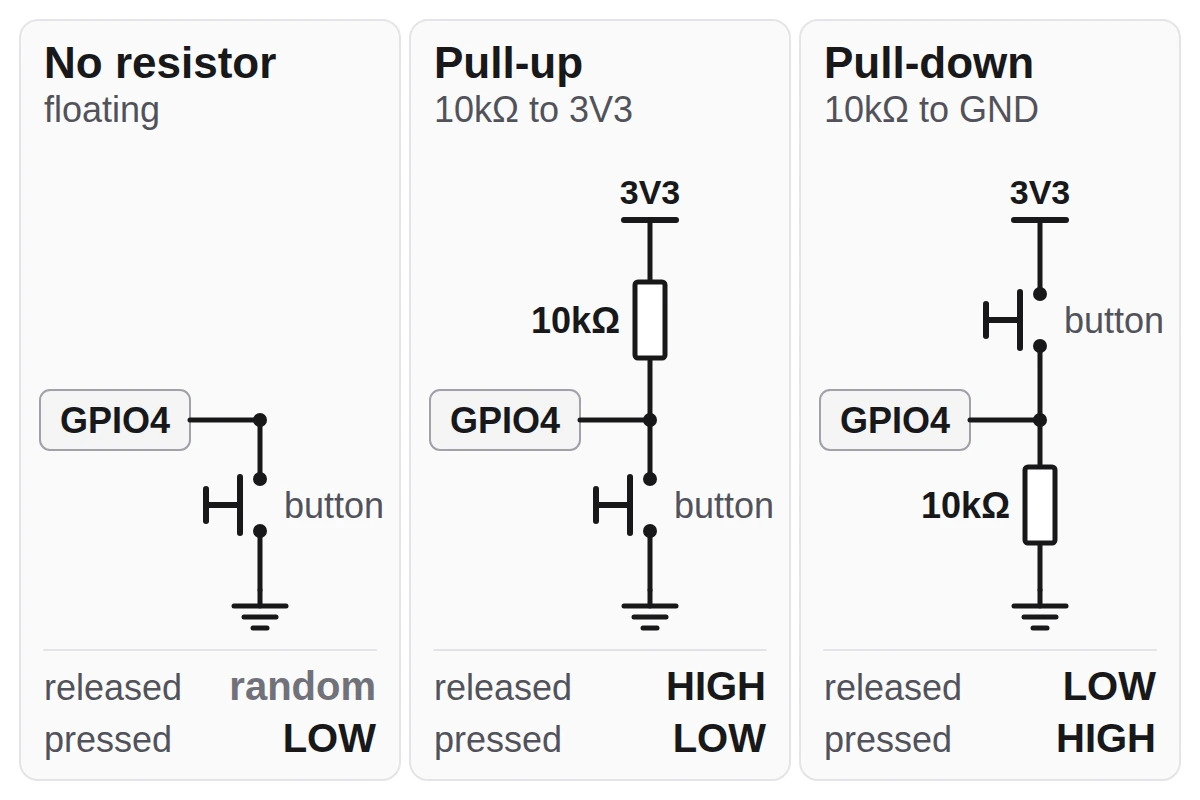
| Pull-up | Pull-down | |
|---|---|---|
| Resistor goes to | 3V3 | GND |
| Button goes to | GND | 3V3 |
| Released reads | HIGH | LOW |
| Pressed reads | LOW | HIGH |
Both do the same job. Most example sketches, including the starter kit's, use a pull-up with the button to GND.
Wire one with the kit's button
The Schematik Starter Kit comes with 6 tactile buttons and a pack of 10kΩ resistors, which is everything you need for both circuits.
For a pull-up on GPIO4:
- Put the button across the center gap of the breadboard.
- Find 2 legs on different sides of the switch: in a multimeter's continuity mode, they beep only while the button is down.
- Connect one of those legs to GPIO4.
- Connect the other to GND.
- Connect a 10kΩ resistor between GPIO4 and 3V3.
The tactile buttons have 4 legs, joined in 2 pairs inside. If the pin reads pressed all the time, your 2 legs are on the same pair.
Then read it:
const int BUTTON_PIN = 4;

void setup() {
  Serial.begin(115200);
  pinMode(BUTTON_PIN, INPUT);  // the 10kΩ resistor does the pulling
}

void loop() {
  if (digitalRead(BUTTON_PIN) == LOW) {
    Serial.println("pressed");
  }
  delay(50);
}
Use the ESP32-S3's built-in pull-ups
Most ESP32-S3 GPIO pins, GPIO4 included, have a pull-up and a pull-down resistor built in, about 45kΩ each. Your code can switch one on, so you can skip the external resistor:
pinMode(BUTTON_PIN, INPUT_PULLUP); // built-in pull-up to 3.3V
With INPUT_PULLUP, wire the button between GPIO4 and GND, with no resistor at all. That's how the starter kit's example projects wire their buttons: the virtual pet reads 3 buttons on GPIO4, GPIO5 and GPIO6 this way. For a built-in pull-down, use INPUT_PULLDOWN instead and wire the button to 3V3.
Your ESP32-S3 board already uses both kinds of pull-up:
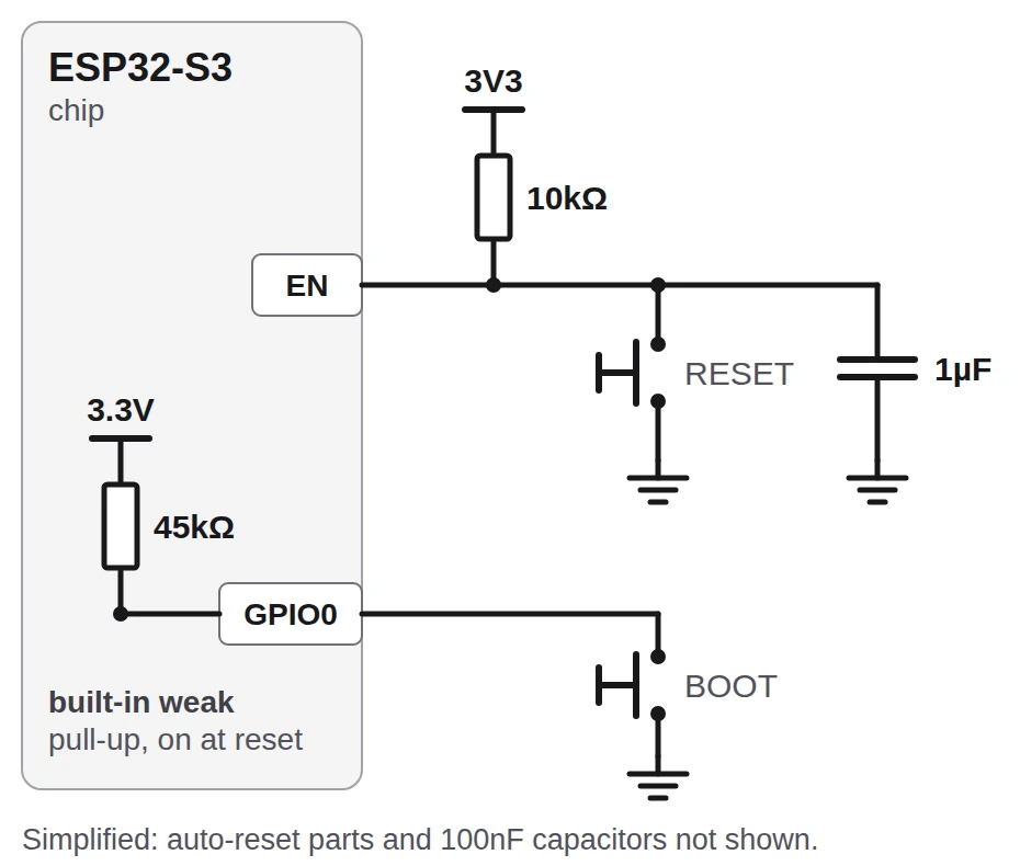
- RESET connects the chip's EN pin to GND. A 10kΩ pull-up on the board holds EN high so the chip runs. Espressif's datasheet is direct about it: "Do not leave the CHIP_PU pin floating."
- BOOT connects GPIO0 to GND. GPIO0 has a weak pull-up inside the chip, on from the moment it powers up. Holding BOOT while you press RESET starts the board in download mode.
When you still want an external pull-up
The built-in resistors cover most buttons. Reach for a real resistor when:
- The pin has no built-in pull-up. On the classic ESP32 (not the S3), GPIO34 to GPIO39 are input-only and have no internal pull-up or pull-down. A button on one of those needs an external resistor.
- It's an I2C bus. I2C is the 2-wire link most small screens and sensors use: SDA carries the data and SCL carries the clock. Both need stronger pull-ups than 45kΩ. The ESP32-S3 datasheet says its I2C speed is limited by pull-up strength. Most I2C modules already carry their own.
- The wire is long or the room is noisy. A 10kΩ resistor holds the pin more firmly than 45kΩ, so stray signals have a harder time moving it.
- The pin must be right before your code runs.
INPUT_PULLUPonly switches on when your sketch reaches that line. If a pin drives something that must stay off during power-up, like a transistor switching a motor, an external pull-down holds it off until your code takes over. Pick a pin like GPIO4, not GPIO18 to GPIO20: the datasheet lists those three as briefly driving HIGH at power-up, which a pull-down can't stop.
Do not add a pull-down to GPIO0, or a pull-up to GPIO45 or GPIO46. The ESP32-S3 reads these pins at reset to decide how to start, and the wrong resistor can stop your sketch from running.
Build something with a button
The arcade reaction tower is a fast reflex game. Its button uses INPUT_PULLUP and connects to GND when pressed, the same circuit as the virtual pet. It's built on a classic ESP32 board, so its pin numbers differ from the ESP32-S3's. Open it in Schematik to get the wiring, parts list and code, then press Deploy.
The desk presence busy light, also on a classic ESP32, uses a button with the built-in pull-up to switch busy mode on and off.
Once your button works, try it the other way round: take the resistor out, move the button's wire from GND to 3V3, change the sketch to INPUT_PULLDOWN and check for HIGH. Does it still print the right thing when you wave your hand near the wires?
Keep building from here
Jump into a step-by-step build, or open Schematik and turn your own idea into code, wiring, and assembly instructions.
Related posts
Related builds
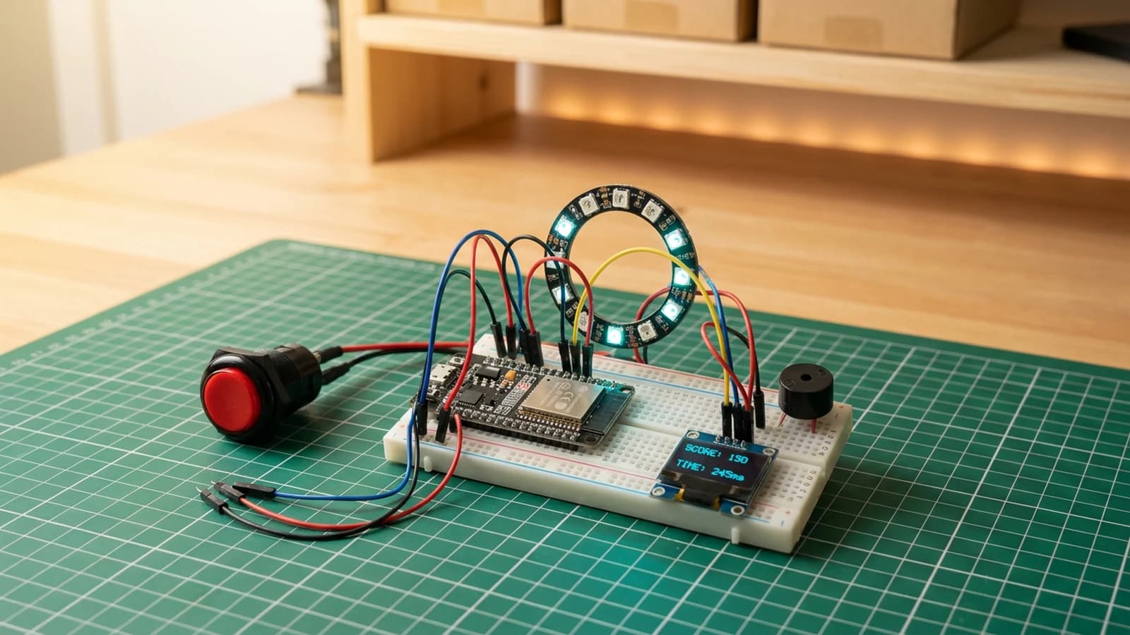
How to Build an Arcade Reaction Tower with ESP32
Build an ESP32 arcade reaction game with WS2812 LED ring, arcade button, buzzer, and OLED score display. Tests reflexes with random light cues.
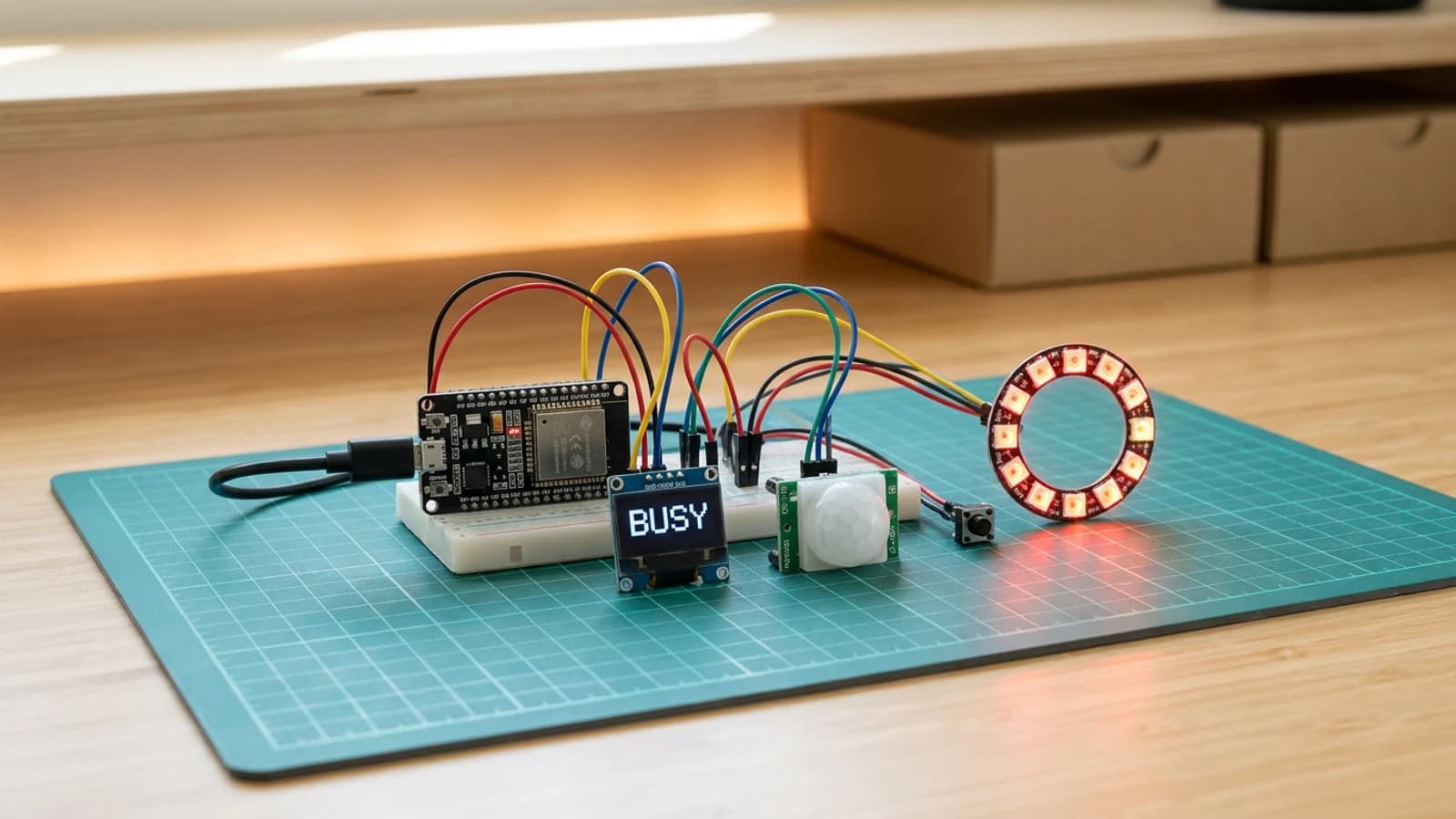
How to Build an ESP32 Desk Presence Busy Light
Build an ESP32 desk presence light that shows whether your workspace is free, recently active, or manually set to busy. Includes PIR wiring, OLED status text, LED ring feedback, and complete Arduino code.