Schematik build
How to Build an Arcade Reaction Tower with ESP32
Fast reflex game with LED cues, score tracking, and victory sounds
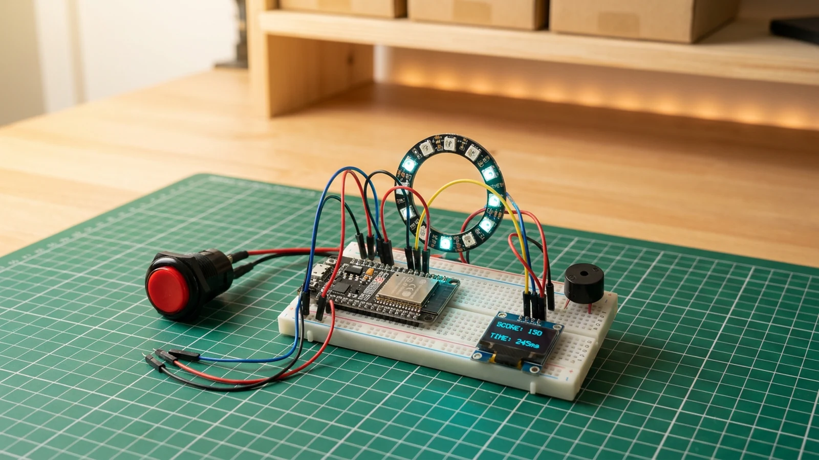
What you'll build
In this guide you will construct an arcade-style reaction tower using an ESP32, a WS2812B LED ring, a large arcade push button, a piezo buzzer, and an OLED score display. The game lights up a random LED on the ring as a cue, and you must press the arcade button as fast as possible before the 2000 ms window closes. Each successful hit earns points based on how quickly you reacted, while a miss triggers a buzzer penalty tone and resets your combo multiplier. The OLED shows your current score, best reaction time, and combo streak in real time, and a victory fanfare plays when you beat your high score.
This build teaches you millisecond-precision timing, random cue generation, and simple scoring with combo multipliers. You will also store the high score in flash memory using the built-in Preferences library, so your best run survives a power cycle without any external storage.
The completed tower is an engaging tabletop game that teaches timing, state management, and LED animation patterns that carry directly into more complex real-time embedded projects. For another interactive prop, see the RFID treasure chest guide.
What you are building
This guide covers a single self-contained reaction game. The firmware has four jobs:
- generate a random delay between 400 ms and 1200 ms, then light one LED on the ring as a cue,
- measure the time between the cue appearing and the button press,
- calculate a score using the formula
max(0, 1500 - reactionMs) * comboand maintain a combo streak, and - play audio feedback through the buzzer and animate the LED ring on hits, misses, and high-score victories.
High scores are persisted in the "arcade" Preferences namespace and survive power loss. Multi-player networking and difficulty selection are out of scope; the codebase is kept intentionally simple so those extensions are straightforward to add yourself.
Upload and calibrate
Flash the sketch from Schematik and open Serial Monitor at 115200 baud.
On first boot the OLED should display a "READY?" screen. Press the arcade button to start a round. The firmware will wait a random time between 400 ms and 1200 ms, then light one LED on the ring as the cue. Press the button before the 2000 ms round timeout expires.
Key constants in the firmware:
LED_PIN 4— data line for the WS2812B ringNUM_LEDS 16— total LEDs on the ring; change this if your ring differsBTN_PIN 27— arcade button inputBUZZER_PIN 26— passive buzzer outputSDA_PIN 21/SCL_PIN 22— I2C pins for the OLED- FastLED global brightness is set to
140; lower it if the ring draws too much current from a shared supply - The round timeout is 2000 ms; a miss resets your combo to 1 and plays a 300 Hz penalty tone
- Scoring:
points = max(0, 1500 - reactionMs) * combo— faster hits score more, and the combo multiplier grows with consecutive hits - A reaction time under 300 ms plays a 2200 Hz tone; a normal hit plays 1200 Hz
- Victory animation (new high score):
fill_rainbowsweep across the ring, three passes, with ascending tones at 1800 Hz, 2200 Hz, and 2600 Hz - High scores are saved to flash in the
"arcade"Preferences namespace under the key"hi"and loaded automatically on boot
If the LED ring flickers or the ESP32 resets when all LEDs light up, your 5 V supply is not providing enough current. A 16-LED WS2812B ring can draw up to 960 mA at full white; a 1 A or 2 A 5 V supply is safer than relying on USB bus power alone.
Troubleshooting
- OLED stays blank after boot. Check SDA is on GPIO 21 and SCL is on GPIO 22. Confirm the display is connected to 3V3, not 5 V. If wiring looks correct, use an I2C scanner sketch to verify the display responds at address 0x3C.
- Button press is not detected or fires repeatedly. The firmware uses INPUT_PULLUP, so the button must connect GPIO 27 to GND when pressed, not to 3V3. A floating or unbounced line can cause phantom presses; check the physical connection.
- LED ring does not light or shows wrong colours. Confirm GPIO 4 reaches 74AHCT125 1A, 1OE is grounded, and 1Y reaches DIN through the 220 Ω resistor. Check that
NUM_LEDSmatches your ring. - ESP32 resets when the LEDs turn on. Confirm the ring and buffer use the dedicated regulated 5 V rail, the bulk capacitor is fitted, and every ground is shared. Lower FastLED brightness from
140if needed. - No sound from the buzzer. Confirm the buzzer is passive (not active) and wired to GPIO 26 with GND on the other terminal. An active buzzer will not respond to the firmware's PWM tone output.
- High score does not survive a power cycle. The
"arcade"Preferences namespace is written to flash on each new high score. If scores are not persisting, check that the ESP32's flash is not being erased on every flash operation — some IDEs erase the full flash by default; use a "sketch only" erase option.
Going further
The scoring formula and round timeout are single constants, which makes adding difficulty modes straightforward. A short timeout (for example 1200 ms) or a shorter cue window makes the game noticeably harder without touching the rest of the logic. You could add a button-hold gesture at the "READY?" screen to cycle through difficulties, storing the selected mode in Preferences alongside the high score.
For a more competitive setup, the ESP32's Wi-Fi makes it practical to send scores to a simple web endpoint or connect two towers over ESP-NOW so two players compete on separate hardware. The game loop's state machine is self-contained, so adding a second player channel is mostly a matter of synchronising the cue trigger and comparing reaction times at the end of each round.
Wiring diagram
Gather all the parts
Assemble it in 5 steps
1. Wire the LED ring
Connect WS2812B 5V to a stable 5V source, GND to ESP32 GND, and DIN to GPIO4.
- Add a 330 Ω resistor on the DIN line and a 470 µF capacitor across LED power.
- Use a separate 5V supply if the ring has more than 8 LEDs.
2. Connect the arcade button and buzzer
Wire the arcade button between GPIO27 and GND. Connect piezo buzzer signal to GPIO26 with the other lead to GND.
- A large arcade-style button is more satisfying and easier to hit fast.
3. Attach the score display
Wire OLED VCC to 3.3V, GND to ground, SDA to GPIO21, and SCL to GPIO22.
- Mount the OLED at eye level for easy score reading during play.
4. Upload and play
Flash the sketch. A random LED lights up — hit the button as fast as possible. Consecutive fast hits build a combo multiplier. High scores persist across power cycles.
- Watch for the random delay between rounds — hitting too early does not count.
5. Add the buffered LED power path
Power the WS2812B ring and 74AHCT125 from the regulated 5 V supply and join its ground to ESP32 ground. Wire GPIO4 to 1A, ground 1OE, and connect 1Y through the 220 Ω resistor to DIN. Put the bulk capacitor across ring 5 V and GND. Tie unused inputs 2A, 3A, and 4A to GND and unused enables 2OE, 3OE, and 4OE to 5 V.
- Place the resistor and capacitor close to the ring.
- Do not power the ring from ESP32 3V3 or drive its 5 V DIN directly from GPIO4.
Review all connections
1. Connections between "arcade-button-1" and "ESP32"
2. Connections between "arcade-buzzer-1" and "ESP32"
3. Connections between "arcade-led-ring-1" and "ESP32"
4. Connections between "arcade-oled-1" and "ESP32"
5. Connections between "arcade-reaction-tower-bulk-capacitor-1" and "ESP32"
6. Connections between "arcade-reaction-tower-led-data-resistor-1" and "ESP32"
7. Connections between "arcade-reaction-tower-logic-level-shifter-1" and "ESP32"
8. Connections between "arcade-reaction-tower-regulated-5v-supply-1" and "ESP32"
9. Connections between "arcade-reaction-tower-usb-c-power-breakout-1" and "ESP32"
Deploy the firmware
#include <Wire.h>
#include <FastLED.h>
#include <Adafruit_SSD1306.h>
#include <Preferences.h>

#define LED_PIN 4
#define NUM_LEDS 16
#define BTN_PIN 27
#define BUZZER_PIN 26
#define SDA_PIN 21
#define SCL_PIN 22

CRGB leds[NUM_LEDS];
Adafruit_SSD1306 display(128, 64, &Wire, -1);
Preferences prefs;

unsigned long roundStart = 0;
bool waitingForPress = false;
int score = 0;
int highScore = 0;
int combo = 0;
int bestReaction = 9999;
int roundCount = 0;

void victoryAnimation() {
  for (int i = 0; i < 3; i++) {
    fill_rainbow(leds, NUM_LEDS, i * 80, 16);
    FastLED.show();
    tone(BUZZER_PIN, 1800 + i * 400, 80);
    delay(120);
  }
}

void setup() {
  Serial.begin(115200);
  delay(100);

  prefs.begin("arcade", false);
  highScore = prefs.getInt("hi", 0);

  Wire.begin(SDA_PIN, SCL_PIN);
  FastLED.addLeds<NEOPIXEL, LED_PIN>(leds, NUM_LEDS);
  FastLED.setBrightness(140);
  display.begin(SSD1306_SWITCHCAPVCC, 0x3C);
  display.setTextSize(1);
  display.setTextColor(SSD1306_WHITE);
  pinMode(BTN_PIN, INPUT_PULLUP);
  pinMode(BUZZER_PIN, OUTPUT);
  randomSeed(micros());

  display.clearDisplay();
  display.setCursor(0, 16);
  display.setTextSize(2);
  display.println(" READY?");
  display.display();
  display.setTextSize(1);
  delay(1200);
}

void loop() {
  if (!waitingForPress) {
    fill_solid(leds, NUM_LEDS, CRGB::Black);
    FastLED.show();
    delay(400 + random(800));

    int target = random(NUM_LEDS);
    leds[target] = CRGB::Orange;
    FastLED.show();
    roundStart = millis();
    waitingForPress = true;
    roundCount++;
  }

  if (waitingForPress && millis() - roundStart > 2000) {
    combo = 0;
    tone(BUZZER_PIN, 300, 200);
    waitingForPress = false;
  }

  if (!digitalRead(BTN_PIN) && waitingForPress) {
    int reactionMs = (int)(millis() - roundStart);
    combo++;
    int points = max(0, 1500 - reactionMs) * combo;
    score += points;
    if (reactionMs < bestReaction) bestReaction = reactionMs;

    bool newHigh = score > highScore;
    if (newHigh) {
      highScore = score;
      prefs.putInt("hi", highScore);
      victoryAnimation();
    } else {
      tone(BUZZER_PIN, reactionMs < 300 ? 2200 : 1200, 70);
    }

    display.clearDisplay();
    display.setCursor(0, 0);
    display.printf("Round: %d\n", roundCount);
    display.printf("React: %dms\n", reactionMs);
    display.printf("Combo: x%d\n", combo);
    display.printf("Score: %d\n", score);
    display.printf("Best:  %dms\n", bestReaction);
    display.printf("High:  %d %s\n", highScore, newHigh ? "NEW!" : "");
    display.display();

    waitingForPress = false;
    delay(300);
  }
}
Remix this project
Make it yours in one click
Open a full copy of this project in your own Schematik workspace — diagram, code, parts, and assembly steps included. Swap the sensor, add features, or redesign the whole thing with AI. The author's original stays untouched.
Related projects
How to Build a Laser Harp Synth with ESP32
ESP32 · Beginner · 40 minutes · June 12, 2026Schematik
How to Build an RFID Treasure Chest with ESP32
ESP32 · Intermediate · 50 minutes · June 12, 2026Schematik
How to Build a ClawdBot Tamagotchi with ESP32
ESP32 · Beginner · 45 minutes · July 22, 2026Schematik