Schematik build
How to Build an ESP32 Desk Presence Busy Light
Motion sensing, manual busy mode, OLED status, and a colour LED ring
What you'll build
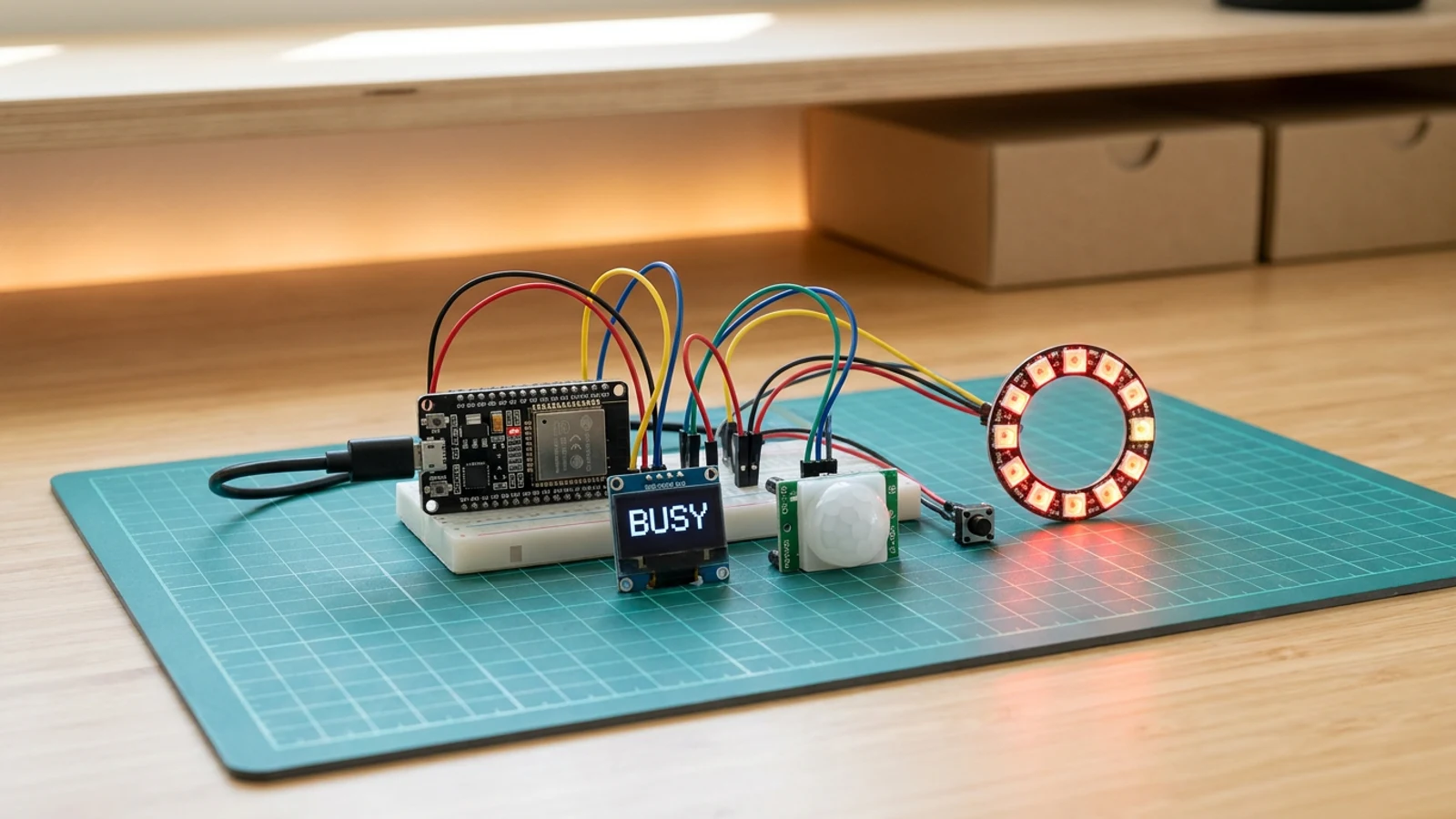
This guide walks you through building a small ESP32 desk presence light that makes your workspace status obvious at a glance. A PIR motion sensor marks the desk as recently active, a tactile button toggles manual busy mode, an SSD1306 OLED shows the current state in plain text, and a WS2812B LED ring changes colour: green for free, orange for recently active, and red when you have set focus mode deliberately.
The build is intentionally practical. You wire a common HC-SR501 PIR module to a digital input, use the ESP32 internal pull-up for the button, share the OLED over I²C, and drive the addressable LED ring from one data pin. No Wi-Fi, no phone app, and no account is required.
By the end you have a useful desk sign for shared studios, home offices, or classrooms where people need a clear signal before interrupting you.
What you are building
This guide produces a standalone presence indicator. The firmware has four jobs:
- poll the HC-SR501 PIR sensor and mark the desk as occupied for
occupiedHoldMsmilliseconds after the last detected motion (default 120 seconds), - debounce the tactile button and toggle manual busy mode on each press,
- update the WS2812B LED ring colour: green (free), orange (recently active), red (manual busy),
- update the SSD1306 OLED with a two-line status: a large label (FREE / HERE / BUSY) and a short detail string.
Out of scope: Wi-Fi reporting, MQTT, Home Assistant integration, and multi-room synchronisation. The code is structured to make those additions straightforward once the physical device works reliably.
Upload and calibrate
Flash the starter sketch from Schematik. There are no Wi-Fi credentials to enter. The only runtime constant worth tuning is occupiedHoldMs, which controls how long the desk stays in the HERE (orange) state after the last detected movement:
occupiedHoldMs— default 120000 (2 minutes). Reduce it if the status takes too long to clear after you leave; increase it if it flickers back to FREE during normal desk use.
After flashing, open Serial Monitor at 115200 baud and verify the board starts. Wave a hand near the PIR; the ring should turn orange and the OLED should show HERE. Press the button; the ring should turn red and the OLED should show BUSY. Press again to return to the automatic state.
If the ring flickers or shows wrong colours, lower FastLED.setBrightness() from 80 to 40 to reduce current draw.
Troubleshooting
- PIR triggers constantly with no movement: the HC-SR501 needs a 30–60 second warm-up after power-on before readings are reliable. Wait a minute after boot before testing.
- PIR never triggers: confirm OUT is wired to GPIO 27, not to the VCC or GND rail. The dome side of the sensor should face the area you want to monitor, not the wall.
- Button toggles twice per press: the firmware debounces with a 350 ms guard on
lastButtonMs. If double-triggering persists, increase that value in the code. - OLED blank, no startup text: check SDA on GPIO 21 and SCL on GPIO 22. Most SSD1306 modules use I²C address 0x3C; confirm with an I²C scanner if the display does not respond.
- LED ring shows wrong colour or stays off: confirm GND is shared between the ring and the ESP32. A loose data wire on GPIO 4 is the most common cause of missing colour output.
- All three states show the same colour: FastLED requires the
NEOPIXELtype and correctNUM_LEDScount. Confirm the ring pixel count matchesNUM_LEDS 12in the code, or adjust it to match your ring.
Going further
The three-state model maps naturally onto MQTT: publish the current state string on each transition and subscribe to a "set busy" topic from another device. That opens up integration with calendar apps, meeting room displays, or a simple Home Assistant automation. On the physical side, replacing the LED ring with a larger diffused enclosure — a frosted ping-pong ball, a lamp shade, or a 3D-printed diffuser — makes the colour visible from across a room without being distracting at close range.
Wiring diagram
Gather all the parts
Assemble it in 4 steps
1. Wire the low-voltage sensor and controls
Power the OLED from ESP32 3V3 and connect SDA to GPIO21 and SCL to GPIO22. Power the HC-SR501 from the 5 V breakout, connect OUT to GPIO27, and connect the button between GPIO26 and GND. All grounds must be common.
2. Build the regulated 5 V LED rail
Plug the 5 V USB-C supply into the socket breakout. Connect breakout VBUS/5V to WS2812B LED ring 5V and 74AHCT125 VCC. Connect breakout GND, ESP32 GND, WS2812B LED ring GND, and 74AHCT125 GND together. Place the bulk capacitor across 5 V and GND at the LEDs, observing polarity. Tie unused inputs 2A, 3A, and 4A to GND and unused enables 2OE, 3OE, and 4OE to 5 V.
- Unplug the supply while wiring. Verify 5 V polarity with a multimeter before connecting the LEDs or ESP32.
3. Buffer the LED data signal
Connect ESP32 GPIO4 to 74AHCT125 input 1A, tie 1OE to GND, and connect output 1Y through the 220 Ω resistor to WS2812B LED ring DIN. Do not connect GPIO4 directly to DIN. Tie unused inputs 2A, 3A, and 4A to GND and unused enables 2OE, 3OE, and 4OE to 5 V.
4. Upload, test, and calibrate
Upload the sketch, open Serial Monitor at 115200 baud, verify every input and output, then perform the calibration described in the guide before enclosing the project.
Review all connections
1. Connections between "button-1" and "ESP32"
2. Connections between "desk-presence-busy-light-bulk-capacitor-1" and "ESP32"
3. Connections between "desk-presence-busy-light-led-data-resistor-1" and "ESP32"
4. Connections between "desk-presence-busy-light-logic-level-shifter-1" and "ESP32"
5. Connections between "desk-presence-busy-light-regulated-5v-supply-1" and "ESP32"
6. Connections between "desk-presence-busy-light-usb-c-power-breakout-1" and "ESP32"
7. Connections between "led-ring-1" and "ESP32"
8. Connections between "oled-1" and "ESP32"
9. Connections between "pir-1" and "ESP32"
Deploy the firmware
#include <Wire.h>
#include <FastLED.h>
#include <Adafruit_SSD1306.h>
#include <Adafruit_GFX.h>

#define PIR_PIN 27
#define BUTTON_PIN 26
#define LED_PIN 4
#define NUM_LEDS 16
#define SDA_PIN 21
#define SCL_PIN 22

Adafruit_SSD1306 display(128, 64, &Wire, -1);
CRGB leds[NUM_LEDS];

bool manualBusy = false;
bool occupied = false;
unsigned long lastMotionMs = 0;
unsigned long lastButtonMs = 0;
const unsigned long occupiedHoldMs = 120000;

void setRing(CRGB color) {
  fill_solid(leds, NUM_LEDS, color);
  FastLED.show();
}

void drawStatus(const char* status, const char* detail) {
  display.clearDisplay();
  display.setTextColor(SSD1306_WHITE);
  display.setTextSize(2);
  display.setCursor(0, 6);
  display.println(status);
  display.setTextSize(1);
  display.setCursor(0, 40);
  display.println(detail);
  display.display();
}

void setup() {
  pinMode(PIR_PIN, INPUT);
  pinMode(BUTTON_PIN, INPUT_PULLUP);
  Wire.begin(SDA_PIN, SCL_PIN);
  FastLED.addLeds<NEOPIXEL, LED_PIN>(leds, NUM_LEDS);
  FastLED.setBrightness(80);
  display.begin(SSD1306_SWITCHCAPVCC, 0x3C);
  drawStatus("FREE", "Wave nearby or press button");
  setRing(CRGB::Green);
}

void loop() {
  if (digitalRead(PIR_PIN) == HIGH) {
    occupied = true;
    lastMotionMs = millis();
  }

  if (digitalRead(BUTTON_PIN) == LOW && millis() - lastButtonMs > 350) {
    manualBusy = !manualBusy;
    lastButtonMs = millis();
  }

  if (occupied && millis() - lastMotionMs > occupiedHoldMs) {
    occupied = false;
  }

  if (manualBusy) {
    setRing(CRGB::Red);
    drawStatus("BUSY", "Manual focus mode");
  } else if (occupied) {
    setRing(CRGB::Orange);
    drawStatus("HERE", "Motion seen at desk");
  } else {
    setRing(CRGB::Green);
    drawStatus("FREE", "No recent motion");
  }

  delay(200);
}
Remix this project
Make it yours in one click
Open a full copy of this project in your own Schematik workspace — diagram, code, parts, and assembly steps included. Swap the sensor, add features, or redesign the whole thing with AI. The author's original stays untouched.
Related projects
How to Build an ESP32 Pomodoro Focus Timer
ESP32 · Beginner · 45 minutes · July 22, 2026Schematik
How to Build a Gesture-Controlled Mood Lamp with ESP32
ESP32 · Beginner · 45 minutes · July 22, 2026Schematik
How to Build an ESP32 Air Quality Monitor with BME280
ESP32 · Beginner · 25 minutes · July 22, 2026Schematik