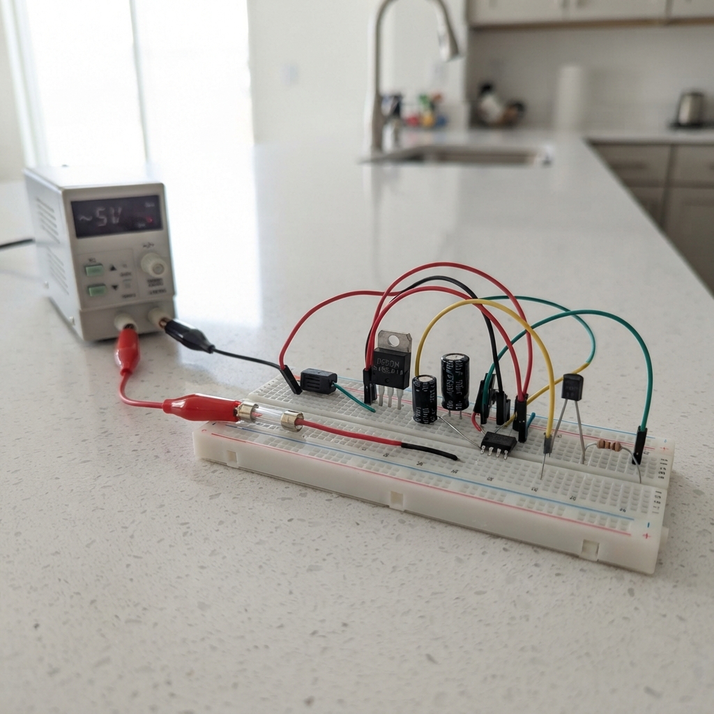
This project builds a 30-cell battery telemetry monitor using an ESP32 to read and log voltage data from a multi-cell battery pack. The system uses RS-485 communication with a BQ79600 AFE controller and BQ79616 monitors in a daisy-chain configuration, along with relay control for diagnostics and heater management. A DC/DC regulator provides stable 5V power while MOSFETs handle relay switching for load control.
The guide provides a complete wiring diagram, parts list, and step-by-step assembly instructions starting with low-voltage simulation before applying full system voltage. Firmware is included to establish a WiFi access point for real-time telemetry monitoring, with careful validation procedures to ensure safe operation of the high-voltage measurement chain.
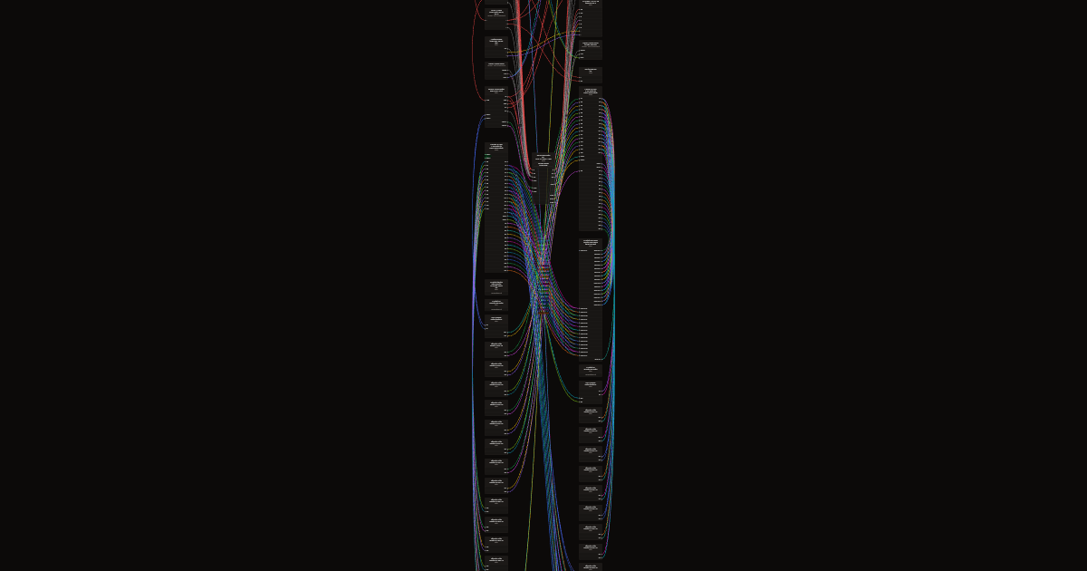
Wiring diagram
Gather all the parts
Assemble it in 9 steps
1. Подготовьте плату и разъём без питания
Не подключайте USB, 14,2 В, жгут или cell simulator. Примерьте 32-контактный корпус к плате, совместите его по механическому ключу и отметьте физические отверстия. При ручной пайке корпус должен быть закреплён механически; паяные выводы не должны быть единственной опорой корпуса.
- Нанесите на плату крупные метки «1», «16», «17» и «32» до пайки.
- Контакт 32 не обжимайте и не подключайте.
- Не сверлите и не паяйте по предполагаемому рисунку: сначала совместите реальный корпус с платой и проверьте, что ключ не позволяет вставить жгут наоборот.
2. Проверьте каждый контакт жгута
Мультиметром в режиме прозвонки, без питания, проверьте путь от каждого контакта состыкованного жгута до отверстия платы. Подпишите провода строго по таблице: контакт 1 → C0, 2 → C1, далее по порядку до 31 → C30; контакт 32 остаётся свободным.
- Начните с отмеченного на корпусе угла «16»: это помогает не перепутать стороны при ручной пайке.
- Сохраните подписанную таблицу рядом со стендом.
- Перестановка даже двух соседних проводов может подать сумму нескольких секций на вход измерительной микросхемы и повредить её.
3. Соберите нижние измерительные входы
Соедините C0…C16 с нижним BQ79616 только через свои 100-омные резисторы: C0 → VC0, C1 → VC1 и так далее до C16 → VC16. Поставьте по одному конденсатору 0,47 мкФ между каждой соседней парой входов VC1–VC0 … VC16–VC15.
- Не соединяйте нижнюю опору AFE с GND ESP32: она относится к C0 лестницы.
4. Соберите верхние измерительные входы
Соедините C16…C30 с верхним BQ79616 через отдельные 100-омные резисторы: C16 → VC0, C17 → VC1 и далее до C30 → VC14. C16 должен идти на два независимых входных резистора: к VC16 нижнего AFE и к VC0 верхнего.
- Не подключайте VC15 и VC16 верхнего AFE к жгуту; их окончательное завершение выполняют только по подтверждённой схеме TI для 14S.
5. Оставьте балансировку выключенной при первом включении
Установите отдельные резисторы балансировки от каждой точки C1…C30 к своему выводу CB AFE, не после 100-омного измерительного резистора. При первом испытании не разрешайте балансировку в прошивке и не подавайте команды CB.
- Нельзя испытывать балансировку на резисторной лестнице, пока не рассчитаны ток, рассеиваемая мощность и число одновременно включённых каналов.
6. Прозвоните плату до подачи напряжения
При отключённом жгуте проверьте каждый путь Cn: отверстие платы → свой 100-омный резистор → правильный VC-вход. Затем проверьте отсутствие короткого замыкания между соседними C-точками, C0 и GND ESP32, а также между CB-выводами.
- Не используйте мультиметр на плате, если к ней подключён источник, USB или cell simulator.
7. Сначала подключите низковольтный имитатор секций
Подайте на лестницу cell simulator заведомо безопасное суммарное напряжение и ограничьте ток источника. Подключайте жгут последовательно от C0, затем C1, C2 и далее до C30; после каждого нового провода измерьте напряжение между новым контактом и предыдущим — оно должно быть только напряжением одной секции.
- Сначала используйте пониженное напряжение одной секции на ступень; так легче обнаружить ошибку нумерации до рабочего диапазона.
- Подключайте C0 первым и C30 последним.
- Никогда не подключайте провода в произвольном порядке и не пропускайте C0: входы AFE могут получить недопустимую разность напряжений.
8. Проверьте измерения и только потом поднимайте напряжение
Когда все 31 провод подключены и показания каждой секции правдоподобны, плавно поднимайте источник лестницы до рабочего диапазона, не превышая 4,33 В между соседними C-точками и 129,9 В суммарно. Контролируйте мультиметром C0–C30 и несколько соседних ступеней.
- Рабочее суммарное напряжение до 129,9 В DC опасно. Не трогайте оголённые контакты, используйте закрытый стенд и изолированные щупы. Реальную батарею не подключайте.
9. Проверьте контроллер отдельно
При отключённом sense-жгуте включите лабораторный источник 14,2 В с ограничением 0,5 А. Измерьте 5 В и 3,3 В, затем подключите USB-C, нажмите Deploy и проверьте, что диагностический контакт без питания остаётся замкнутым между COM и NC.
- Не используйте USB как подтверждение исправности измерительного тракта: измерение ячеек проверяется только на контролируемом cell simulator.
Review all connections
1. Connections between "lab_supply_14v2" and "ESP32"
2. Connections between "buck_5v" and "ESP32"
3. Connections between "input_capacitor" and "ESP32"
4. Connections between "output_capacitor" and "ESP32"
5. Connections between "rs485_1" and "ESP32"
6. Connections between "diagnostic_mosfet" and "ESP32"
7. Connections between "diagnostic_gate_resistor" and "ESP32"
8. Connections between "diagnostic_gate_pulldown" and "ESP32"
9. Connections between "heater_mosfet" and "ESP32"
10. Connections between "heater_gate_resistor" and "ESP32"
11. Connections between "heater_gate_pulldown" and "ESP32"
12. Connections between "bq79600_bridge" and "ESP32"
13. Connections between "com_iso_bridge_lower" and "ESP32"
14. Connections between "bq79616_lower" and "ESP32"
15. Connections between "com_iso_lower_upper" and "ESP32"
16. Connections between "bq79616_upper" and "ESP32"
17. Connections between "upper_com_termination" and "ESP32"
18. Connections between "bq79600_bat_filter_resistor" and "ESP32"
19. Connections between "bq79600_bat_bypass" and "ESP32"
20. Connections between "bq79600_cvdd_bypass" and "ESP32"
21. Connections between "bq79600_vio_bypass" and "ESP32"
22. Connections between "balance_r_c1" and "ESP32"
23. Connections between "balance_r_c2" and "ESP32"
24. Connections between "balance_r_c3" and "ESP32"
25. Connections between "balance_r_c4" and "ESP32"
26. Connections between "balance_r_c5" and "ESP32"
27. Connections between "balance_r_c6" and "ESP32"
28. Connections between "balance_r_c7" and "ESP32"
29. Connections between "balance_r_c8" and "ESP32"
30. Connections between "balance_r_c9" and "ESP32"
31. Connections between "balance_r_c10" and "ESP32"
32. Connections between "balance_r_c11" and "ESP32"
33. Connections between "balance_r_c12" and "ESP32"
34. Connections between "balance_r_c13" and "ESP32"
35. Connections between "balance_r_c14" and "ESP32"
36. Connections between "balance_r_c15" and "ESP32"
37. Connections between "balance_r_c16" and "ESP32"
38. Connections between "balance_r_c17" and "ESP32"
39. Connections between "balance_r_c18" and "ESP32"
40. Connections between "balance_r_c19" and "ESP32"
41. Connections between "balance_r_c20" and "ESP32"
42. Connections between "balance_r_c21" and "ESP32"
43. Connections between "balance_r_c22" and "ESP32"
44. Connections between "balance_r_c23" and "ESP32"
45. Connections between "balance_r_c24" and "ESP32"
46. Connections between "balance_r_c25" and "ESP32"
47. Connections between "balance_r_c26" and "ESP32"
48. Connections between "balance_r_c27" and "ESP32"
49. Connections between "balance_r_c28" and "ESP32"
50. Connections between "balance_r_c29" and "ESP32"
51. Connections between "balance_r_c30" and "ESP32"
52. Connections between "vc_l_0_r" and "ESP32"
53. Connections between "vc_l_1_r" and "ESP32"
54. Connections between "vc_l_2_r" and "ESP32"
55. Connections between "vc_l_3_r" and "ESP32"
56. Connections between "vc_l_4_r" and "ESP32"
57. Connections between "vc_l_5_r" and "ESP32"
58. Connections between "vc_l_6_r" and "ESP32"
59. Connections between "vc_l_7_r" and "ESP32"
60. Connections between "vc_l_8_r" and "ESP32"
61. Connections between "vc_l_9_r" and "ESP32"
62. Connections between "vc_l_10_r" and "ESP32"
63. Connections between "vc_l_11_r" and "ESP32"
64. Connections between "vc_l_12_r" and "ESP32"
65. Connections between "vc_l_13_r" and "ESP32"
66. Connections between "vc_l_14_r" and "ESP32"
67. Connections between "vc_l_15_r" and "ESP32"
68. Connections between "vc_l_16_r" and "ESP32"
69. Connections between "vc_u_0_r" and "ESP32"
70. Connections between "vc_u_1_r" and "ESP32"
71. Connections between "vc_u_2_r" and "ESP32"
72. Connections between "vc_u_3_r" and "ESP32"
73. Connections between "vc_u_4_r" and "ESP32"
74. Connections between "vc_u_5_r" and "ESP32"
75. Connections between "vc_u_6_r" and "ESP32"
76. Connections between "vc_u_7_r" and "ESP32"
77. Connections between "vc_u_8_r" and "ESP32"
78. Connections between "vc_u_9_r" and "ESP32"
79. Connections between "vc_u_10_r" and "ESP32"
80. Connections between "vc_u_11_r" and "ESP32"
81. Connections between "vc_u_12_r" and "ESP32"
82. Connections between "vc_u_13_r" and "ESP32"
83. Connections between "vc_u_14_r" and "ESP32"
84. Connections between "vc_l_1_c" and "ESP32"
85. Connections between "vc_l_2_c" and "ESP32"
86. Connections between "vc_l_3_c" and "ESP32"
87. Connections between "vc_l_4_c" and "ESP32"
88. Connections between "vc_l_5_c" and "ESP32"
89. Connections between "vc_l_6_c" and "ESP32"
90. Connections between "vc_l_7_c" and "ESP32"
91. Connections between "vc_l_8_c" and "ESP32"
92. Connections between "vc_l_9_c" and "ESP32"
93. Connections between "vc_l_10_c" and "ESP32"
94. Connections between "vc_l_11_c" and "ESP32"
95. Connections between "vc_l_12_c" and "ESP32"
96. Connections between "vc_l_13_c" and "ESP32"
97. Connections between "vc_l_14_c" and "ESP32"
98. Connections between "vc_l_15_c" and "ESP32"
99. Connections between "vc_l_16_c" and "ESP32"
100. Connections between "vc_u_1_c" and "ESP32"
101. Connections between "vc_u_2_c" and "ESP32"
102. Connections between "vc_u_3_c" and "ESP32"
103. Connections between "vc_u_4_c" and "ESP32"
104. Connections between "vc_u_5_c" and "ESP32"
105. Connections between "vc_u_6_c" and "ESP32"
106. Connections between "vc_u_7_c" and "ESP32"
107. Connections between "vc_u_8_c" and "ESP32"
108. Connections between "vc_u_9_c" and "ESP32"
109. Connections between "vc_u_10_c" and "ESP32"
110. Connections between "vc_u_11_c" and "ESP32"
111. Connections between "vc_u_12_c" and "ESP32"
112. Connections between "vc_u_13_c" and "ESP32"
113. Connections between "vc_u_14_c" and "ESP32"
114. Connections between "input_fuse" and "ESP32"
115. Connections between "reverse_polarity_mosfet" and "ESP32"
116. Connections between "input_tvs" and "ESP32"
117. Connections between "ldo_3v3" and "ESP32"
118. Connections between "bq79600_dvdd_bypass" and "ESP32"
119. Connections between "relay_diag" and "ESP32"
120. Connections between "flyback_diag" and "ESP32"
121. Connections between "relay_heat" and "ESP32"
122. Connections between "flyback_heat" and "ESP32"
123. Connections between "rs485_terminal" and "ESP32"
Deploy the firmware
#include <Arduino.h>
#include <WiFi.h>
#include <WebServer.h>
#include <Preferences.h>
#include <math.h>

// Только стендовая прошивка. Утверждённая архитектура AFE: один мост BQ79600
// и два монитора BQ79616 в дифференциальной daisy-chain-цепочке для 30 ячеек.
// До проверки специализированной AFE-платы с RC-фильтрами и маломощного cell simulator
// единственным источником отображаемых величин остаётся симуляция.
static const char *DEFAULT_AP_SSID = "BMS-Bench";
static const char *DEFAULT_AP_PASSWORD = "bench-setup-2026";
static const size_t WIFI_SSID_MAX_LEN = 32;
static const size_t WIFI_PASSWORD_MAX_LEN = 63;
char wifiSsid[WIFI_SSID_MAX_LEN + 1] = {};
char wifiPassword[WIFI_PASSWORD_MAX_LEN + 1] = {};
static const uint32_t REPORT_INTERVAL_MS = 5000;
// Низковольтная полудуплексная стендовая линия RS-485. ESP32-S3 поддерживает маршрутизацию через GPIO-матрицу.
static const int RS485_DI_PIN = 17;
static const int RS485_RO_PIN = 18;
static const int RS485_DE_PIN = 21;
// GPIO4 управляет 2N7000, который тянет активный-низкий вход IN1 релейного модуля к земле.
// Это включает канал 1 и размыкает диагностический контакт COM1–NC1.
static const int DIAGNOSTIC_RELAY_PIN = 4;
// GPIO5 управляет вторым 2N7000, который тянет активный-низкий вход IN2 к земле.
// Контакт COM2–NO2 канала 2 — только сухой запрос внешнему утверждённому контроллеру нагрева.
static const int HEATER_RELAY_PIN = 5;
// Утверждённый хост-UART BQ79600 в низковольтной части ESP32.
// ESP32 TX GPIO6 идёт на BQ79600 HOST_RX; BQ79600 HOST_TX идёт на ESP32 RX GPIO7.
// Эта линия электрически отделена от плавающей цепочки измерителей ячеек BQ79616.
static const int BQ79600_HOST_TX_PIN = 6;
static const int BQ79600_HOST_RX_PIN = 7;
static const uint32_t BQ79600_HOST_BAUD = 1000000;
static const uint32_t RS485_BAUD = 9600;
static const uint8_t AFE_COUNT = 2;
// The physical chain is asymmetric: lower BQ79616 measures C0…C16 (16 cells),
// upper BQ79616 measures C16…C30 (14 cells). C16 is the one shared tap.
static const uint8_t LOWER_AFE_CELL_COUNT = 16;
static const uint8_t UPPER_AFE_CELL_COUNT = 14;
static const uint8_t CELL_COUNT = LOWER_AFE_CELL_COUNT + UPPER_AFE_CELL_COUNT;
static const float DEFAULT_CELL_MIN_V = 2.70F;
static const float DEFAULT_CELL_MAX_V = 4.25F;
static const float DEFAULT_TEMP_MIN_C = -20.0F;
static const float DEFAULT_TEMP_MAX_C = 60.0F;
static const uint8_t TEMP_SENSOR_COUNT = 10;  // Five isolated NTC channels per planned AFE.

struct AlarmLimits {
  float cellMinV;
  float cellMaxV;
  float tempMinC;
  float tempMaxC;
};

struct HeaterSettings {
  bool enabled;
  float startBelowC;   // Request heat when the coldest valid sensor is below this value.
  float stopAtC;       // Remove the request when every valid sensor is at or above this value.
  float inhibitAtC;    // Never request heat at or above this safety ceiling.
};

// This permission can be changed only through the local web form. It is never
// taken from Modbus, survives no unsafe boot state, and is blocked in simulation.
struct BalanceSettings {
  bool enabled;
  float startDeltaV;
  float stopDeltaV;
  float minimumCellV;
  uint16_t maximumMinutes;
};

struct AfeStatus {
  bool communicationOk;
  bool measurementsValid;
  bool ntcOpen;
  bool ntcShort;
  bool openWire;
  bool fault;
  float cellVoltage[CELL_COUNT];
  float temperatureC[TEMP_SENSOR_COUNT];
};

WebServer server(80);
Preferences preferences;
AfeStatus afe = {};
AlarmLimits limits = {DEFAULT_CELL_MIN_V, DEFAULT_CELL_MAX_V, DEFAULT_TEMP_MIN_C, DEFAULT_TEMP_MAX_C};
// Disabled by default: an operator must explicitly enable the dry-contact request after
// confirming the off-board thermal appliance and its independent protection.
HeaterSettings heater = {false, 5.0F, 8.0F, 45.0F};
bool heaterRequestActive = false;
BalanceSettings balance = {false, 0.030F, 0.015F, 3.00F, 5};
bool balanceCommandActive = false;
// No BQ79600 packet transport, AFE enumeration, CRC verification, or CB readback
// has been validated on this hardware. Never change this from false in the field.
static const bool BQ_BALANCE_TRANSPORT_VALIDATED = false;
uint32_t lastReportMs = 0;
static const uint16_t HISTORY_POINTS = 120;  // Two minutes at one sample per second.
static const uint32_t HISTORY_INTERVAL_MS = 1000;
float cellMinimum[CELL_COUNT];
float cellMaximum[CELL_COUNT];
float cellHistory[CELL_COUNT][HISTORY_POINTS];
uint16_t historyWriteIndex = 0;
uint16_t historyCount = 0;
uint32_t lastHistoryMs = 0;
uint32_t measurementVersion = 0;
uint32_t rs485RxBytes = 0;
uint32_t rs485TxFrames = 0;
bool simulationEnabled = true;
uint8_t modbusAddress = 1;

enum NetworkRole : uint8_t { MODBUS_SLAVE = 0, MODBUS_MASTER = 1 };
static const uint8_t MAX_REMOTE_MODULES = 5;
NetworkRole networkRole = MODBUS_SLAVE;
uint8_t masterFirstAddress = 1;
uint8_t masterModuleCount = 2;
struct RemoteModuleStatus {
  bool online;
  bool dataValid;
  bool fault;
  uint32_t lastReplyMs;
  // Last complete register image received from this slave. These are displayed
  // as remote diagnostic values; they never command a battery or contactor.
  float cellVoltage[CELL_COUNT];
  float temperatureC[TEMP_SENSOR_COUNT];
};
RemoteModuleStatus remoteModules[MAX_REMOTE_MODULES] = {};
uint8_t masterNextModule = 0;
int8_t masterWaitingModule = -1;
uint32_t masterRequestMs = 0;
uint32_t masterLastPollMs = 0;
uint32_t masterRequests = 0;
uint32_t masterReplies = 0;
uint32_t masterTimeouts = 0;

// The master broadcasts this health marker only while every configured slave is
// present, valid, and not faulted. Each slave fails safe until it has received it.
static const uint16_t MASTER_HEALTH_REGISTER = 45;
static const uint16_t MASTER_HEALTH_MARKER = 0xA55A;
static const uint32_t MASTER_HEALTH_INTERVAL_MS = 1000;
// Every fault condition must remain present continuously for five seconds before
// this module energizes its relay and opens COM-NC.
static const uint32_t FAULT_DELAY_MS = 5000;
// A received heartbeat clears the running fault timer. If it stops, the common
// five-second FAULT_DELAY_MS starts from the last received heartbeat.
static const uint32_t MASTER_HEALTH_TIMEOUT_MS = 0;
bool masterHealthSeen = false;
uint32_t lastMasterHealthMs = 0;
uint32_t lastMasterHealthBroadcastMs = 0;
uint32_t faultStartedMs = 0;
bool faultDelayRunning = false;
bool delayedFaultActive = false;

uint8_t modbusFrame[128] = {};
size_t modbusFrameLength = 0;
uint32_t modbusLastByteMs = 0;
uint32_t lastSimulationMs = 0;

static bool measurementsTrusted() {
  return afe.communicationOk && afe.measurementsValid && !afe.ntcOpen &&
         !afe.ntcShort && !afe.openWire && !afe.fault;
}

static bool localMeasurementFault() {
  // Simulation is deliberately diagnostic-only, never valid battery data.
  if (simulationEnabled || !measurementsTrusted()) return true;
  for (uint8_t index = 0; index < CELL_COUNT; ++index) {
    const float value = afe.cellVoltage[index];
    if (isnan(value) || value < limits.cellMinV || value > limits.cellMaxV) return true;
  }
  for (uint8_t index = 0; index < TEMP_SENSOR_COUNT; ++index) {
    const float value = afe.temperatureC[index];
    if (isnan(value) || value < limits.tempMinC || value > limits.tempMaxC) return true;
  }
  return false;
}

static bool rawFaultPresent() {
  if (networkRole == MODBUS_MASTER) {
    for (uint8_t index = 0; index < masterModuleCount; ++index) {
      const RemoteModuleStatus &module = remoteModules[index];
      if (!module.online || !module.dataValid || module.fault || millis() - module.lastReplyMs > 3000U) return true;
    }
    return false;
  }
  if (!masterHealthSeen || millis() - lastMasterHealthMs > MASTER_HEALTH_TIMEOUT_MS) return true;
  return localMeasurementFault();
}

static void updateFaultDelay() {
  if (!rawFaultPresent()) {
    faultDelayRunning = false;
    delayedFaultActive = false;
    return;
  }
  if (!faultDelayRunning) {
    faultDelayRunning = true;
    faultStartedMs = millis();
  }
  if (millis() - faultStartedMs >= FAULT_DELAY_MS) delayedFaultActive = true;
}

static bool anyLimitExceeded() {
  return delayedFaultActive;
}

static bool diagnosticRelayCoilCommand() {
  // Normal state is coil off, therefore COM-NC is closed. A sustained FAULT opens COM-NC.
  return anyLimitExceeded();
}

static void updateDiagnosticRelay() {
  // HIGH turns on the external 2N7000, which pulls active-low relay-module IN1 down.
  digitalWrite(DIAGNOSTIC_RELAY_PIN, diagnosticRelayCoilCommand() ? HIGH : LOW);
}

static bool heaterTemperaturesAvailable(float &minimumC, float &maximumC) {
  minimumC = NAN;
  maximumC = NAN;
  if (networkRole == MODBUS_MASTER) {
    // A master may request heat only when every configured slave is online, valid,
    // fault-free and current. rawFaultPresent() enforces all of those conditions.
    if (rawFaultPresent()) return false;
    for (uint8_t module = 0; module < masterModuleCount; ++module) {
      for (uint8_t sensor = 0; sensor < TEMP_SENSOR_COUNT; ++sensor) {
        const float value = remoteModules[module].temperatureC[sensor];
        if (isnan(value)) return false;
        if (isnan(minimumC) || value < minimumC) minimumC = value;
        if (isnan(maximumC) || value > maximumC) maximumC = value;
      }
    }
  } else {
    // Simulator and every AFE/NTC/sense fault are deliberately ineligible.
    if (localMeasurementFault()) return false;
    for (uint8_t sensor = 0; sensor < TEMP_SENSOR_COUNT; ++sensor) {
      const float value = afe.temperatureC[sensor];
      if (isnan(value)) return false;
      if (isnan(minimumC) || value < minimumC) minimumC = value;
      if (isnan(maximumC) || value > maximumC) maximumC = value;
    }
  }
  return !isnan(minimumC) && !isnan(maximumC);
}

static void updateHeaterController() {
  float minimumC, maximumC;
  if (!heater.enabled || !heaterTemperaturesAvailable(minimumC, maximumC) ||
      maximumC >= heater.inhibitAtC) {
    heaterRequestActive = false;
  } else if (!heaterRequestActive && minimumC < heater.startBelowC) {
    heaterRequestActive = true;
  } else if (heaterRequestActive && minimumC >= heater.stopAtC) {
    heaterRequestActive = false;
  }
  // HIGH turns on the external 2N7000, which pulls active-low relay-module IN2 down.
  digitalWrite(HEATER_RELAY_PIN, heaterRequestActive ? HIGH : LOW);
}

static bool readPostedFloat(const char *name, float &value) {
  if (!server.hasArg(name)) return false;
  const float parsed = server.arg(name).toFloat();
  if (isnan(parsed)) return false;
  value = parsed;
  return true;
}

static bool limitsAreSafe(const AlarmLimits &candidate) {
  return candidate.cellMinV >= 0.0F && candidate.cellMinV < candidate.cellMaxV &&
         candidate.cellMaxV <= 5.0F && candidate.tempMinC >= -40.0F &&
         candidate.tempMinC < candidate.tempMaxC && candidate.tempMaxC <= 125.0F;
}

static bool heaterSettingsAreSafe(const HeaterSettings &candidate) {
  return candidate.startBelowC >= -40.0F && candidate.startBelowC < candidate.stopAtC &&
         candidate.stopAtC < candidate.inhibitAtC && candidate.inhibitAtC <= 125.0F;
}

static bool balanceSettingsAreSafe(const BalanceSettings &candidate) {
  return candidate.startDeltaV >= 0.005F && candidate.startDeltaV <= 0.500F &&
         candidate.stopDeltaV >= 0.001F && candidate.stopDeltaV < candidate.startDeltaV &&
         candidate.minimumCellV >= 0.0F && candidate.minimumCellV <= 5.0F &&
         candidate.maximumMinutes >= 1 && candidate.maximumMinutes <= 30;
}

static bool balanceRequestEligible() {
  if (!balance.enabled || simulationEnabled || networkRole != MODBUS_SLAVE ||
      localMeasurementFault() || anyLimitExceeded()) return false;
  float minimum = NAN, maximum = NAN;
  for (uint8_t cell = 0; cell < CELL_COUNT; ++cell) {
    const float value = afe.cellVoltage[cell];
    if (isnan(value) || value < balance.minimumCellV) return false;
    if (isnan(minimum) || value < minimum) minimum = value;
    if (isnan(maximum) || value > maximum) maximum = value;
  }
  return !isnan(minimum) && !isnan(maximum) && maximum - minimum >= balance.startDeltaV;
}

static void updateBalanceController() {
  // This is the all-off state. It is reached at boot, reset, simulation, fault,
  // loss of data, and whenever the local web permission is removed.
  balanceCommandActive = false;
  if (!balanceRequestEligible() || !BQ_BALANCE_TRANSPORT_VALIDATED) return;
  // A real command may be added only with a validated BQ79600/BQ79616 transport,
  // all-channel-off frame, status readback, timing limit, and cell-simulator test.
}

static bool wifiSettingsAreSafe(const String &ssid, const String &password) {
  return ssid.length() >= 1 && ssid.length() <= WIFI_SSID_MAX_LEN &&
         password.length() >= 8 && password.length() <= WIFI_PASSWORD_MAX_LEN;
}

static void loadSettings() {
  preferences.begin("bms-settings", false);
  limits.cellMinV = preferences.getFloat("cell-min", DEFAULT_CELL_MIN_V);
  limits.cellMaxV = preferences.getFloat("cell-max", DEFAULT_CELL_MAX_V);
  limits.tempMinC = preferences.getFloat("temp-min", DEFAULT_TEMP_MIN_C);
  limits.tempMaxC = preferences.getFloat("temp-max", DEFAULT_TEMP_MAX_C);
  if (!limitsAreSafe(limits)) limits = {DEFAULT_CELL_MIN_V, DEFAULT_CELL_MAX_V, DEFAULT_TEMP_MIN_C, DEFAULT_TEMP_MAX_C};
  heater.enabled = preferences.getBool("heat-enable", false);
  heater.startBelowC = preferences.getFloat("heat-start", 5.0F);
  heater.stopAtC = preferences.getFloat("heat-stop", 8.0F);
  heater.inhibitAtC = preferences.getFloat("heat-inhibit", 45.0F);
  if (!heaterSettingsAreSafe(heater)) heater = {false, 5.0F, 8.0F, 45.0F};
  balance.enabled = preferences.getBool("bal-enable", false);
  balance.startDeltaV = preferences.getFloat("bal-start", 0.030F);
  balance.stopDeltaV = preferences.getFloat("bal-stop", 0.015F);
  balance.minimumCellV = preferences.getFloat("bal-min-v", 3.00F);
  balance.maximumMinutes = preferences.getUShort("bal-max-min", 5);
  if (!balanceSettingsAreSafe(balance)) balance = {false, 0.030F, 0.015F, 3.00F, 5};

  simulationEnabled = preferences.getBool("simulate", true);
  modbusAddress = preferences.getUChar("mb-addr", 1);
  if (modbusAddress < 1 || modbusAddress > 247) modbusAddress = 1;
  networkRole = preferences.getUChar("mb-role", MODBUS_SLAVE) == MODBUS_MASTER ? MODBUS_MASTER : MODBUS_SLAVE;
  masterFirstAddress = preferences.getUChar("mb-first", 1);
  masterModuleCount = preferences.getUChar("mb-count", 2);
  if (masterFirstAddress < 1 || masterFirstAddress > 247) masterFirstAddress = 1;
  if (masterModuleCount < 1 || masterModuleCount > MAX_REMOTE_MODULES || masterFirstAddress + masterModuleCount - 1 > 247) masterModuleCount = 2;
  const String storedSsid = preferences.getString("wifi-ssid", DEFAULT_AP_SSID);
  const String storedPassword = preferences.getString("wifi-pass", DEFAULT_AP_PASSWORD);
  if (wifiSettingsAreSafe(storedSsid, storedPassword)) {
    storedSsid.toCharArray(wifiSsid, sizeof(wifiSsid));
    storedPassword.toCharArray(wifiPassword, sizeof(wifiPassword));
  } else {
    strlcpy(wifiSsid, DEFAULT_AP_SSID, sizeof(wifiSsid));
    strlcpy(wifiPassword, DEFAULT_AP_PASSWORD, sizeof(wifiPassword));
  }
}

static void saveSettings() {
  preferences.putFloat("cell-min", limits.cellMinV);
  preferences.putFloat("cell-max", limits.cellMaxV);
  preferences.putFloat("temp-min", limits.tempMinC);
  preferences.putFloat("temp-max", limits.tempMaxC);
  preferences.putBool("heat-enable", heater.enabled);
  preferences.putFloat("heat-start", heater.startBelowC);
  preferences.putFloat("heat-stop", heater.stopAtC);
  preferences.putFloat("heat-inhibit", heater.inhibitAtC);
  preferences.putBool("bal-enable", balance.enabled);
  preferences.putFloat("bal-start", balance.startDeltaV);
  preferences.putFloat("bal-stop", balance.stopDeltaV);
  preferences.putFloat("bal-min-v", balance.minimumCellV);
  preferences.putUShort("bal-max-min", balance.maximumMinutes);
  preferences.putBool("simulate", simulationEnabled);
  preferences.putUChar("mb-addr", modbusAddress);
  preferences.putUChar("mb-role", networkRole);
  preferences.putUChar("mb-first", masterFirstAddress);
  preferences.putUChar("mb-count", masterModuleCount);
  preferences.putString("wifi-ssid", wifiSsid);
  preferences.putString("wifi-pass", wifiPassword);
}

static void clearCellRecords() {
  for (uint8_t cell = 0; cell < CELL_COUNT; ++cell) {
    cellMinimum[cell] = NAN;
    cellMaximum[cell] = NAN;
    for (uint16_t point = 0; point < HISTORY_POINTS; ++point) cellHistory[cell][point] = NAN;
  }
  historyWriteIndex = 0;
  historyCount = 0;
  measurementVersion++;
}

// Call only after a complete, CRC-checked BQ measurement updates afe.cellVoltage.
// Invalid readings are deliberately never retained as extrema or plotted samples.
static void recordValidAfeSample() {
  if (!measurementsTrusted()) return;
  for (uint8_t cell = 0; cell < CELL_COUNT; ++cell) if (isnan(afe.cellVoltage[cell])) return;
  for (uint8_t cell = 0; cell < CELL_COUNT; ++cell) {
    const float v = afe.cellVoltage[cell];
    if (isnan(cellMinimum[cell]) || v < cellMinimum[cell]) cellMinimum[cell] = v;
    if (isnan(cellMaximum[cell]) || v > cellMaximum[cell]) cellMaximum[cell] = v;
    cellHistory[cell][historyWriteIndex] = v;
  }
  historyWriteIndex = (historyWriteIndex + 1U) % HISTORY_POINTS;
  if (historyCount < HISTORY_POINTS) historyCount++;
  measurementVersion++;
}

static void sampleHistoryIfDue() {
  const uint32_t now = millis();
  if (now - lastHistoryMs < HISTORY_INTERVAL_MS) return;
  lastHistoryMs = now;
  recordValidAfeSample();
}

static void appendNumberOrNull(String &json, float value) {
  if (isnan(value)) json += F("null"); else json += String(value, 4);
}

static uint16_t modbusCrc(const uint8_t *data, size_t length) {
  uint16_t crc = 0xFFFF;
  for (size_t i = 0; i < length; ++i) {
    crc ^= data[i];
    for (uint8_t bit = 0; bit < 8; ++bit) crc = (crc & 1U) ? (crc >> 1U) ^ 0xA001U : crc >> 1U;
  }
  return crc;
}

static void sendModbusFrame(uint8_t *data, size_t length) {
  const uint16_t crc = modbusCrc(data, length);
  data[length++] = static_cast<uint8_t>(crc & 0xFFU);
  data[length++] = static_cast<uint8_t>(crc >> 8U);
  digitalWrite(RS485_DE_PIN, HIGH);
  delayMicroseconds(30);
  Serial1.write(data, length);
  Serial1.flush();
  delayMicroseconds(30);
  digitalWrite(RS485_DE_PIN, LOW);
  ++rs485TxFrames;
}

static uint16_t simulationRegister(uint16_t address) {
  if (address == 0) return measurementsTrusted() ? 0x0001 : 0x0000; // bit 0: valid simulated data
  if (address == 1) return CELL_COUNT;
  if (address >= 2 && address < 2 + CELL_COUNT) return static_cast<uint16_t>(lroundf(afe.cellVoltage[address - 2] * 1000.0F));
  if (address >= 34 && address < 34 + TEMP_SENSOR_COUNT) return static_cast<uint16_t>(static_cast<int16_t>(lroundf(afe.temperatureC[address - 34] * 10.0F)));
  // Report the slave's own measurement fault immediately so a master can begin
  // its independent five-second delay at the same time. The slave's relay still
  // waits for its own delay before it changes state.
  if (address == 44) return localMeasurementFault() ? 1 : 0;
  return 0;
}

static void processModbusRequest() {
  if (networkRole != MODBUS_SLAVE || modbusFrameLength < 8) return;
  const uint16_t receivedCrc = static_cast<uint16_t>(modbusFrame[modbusFrameLength - 2]) | (static_cast<uint16_t>(modbusFrame[modbusFrameLength - 1]) << 8U);
  if (modbusCrc(modbusFrame, modbusFrameLength - 2) != receivedCrc) return;
  const uint8_t address = modbusFrame[0];
  const uint8_t function = modbusFrame[1];

  // Modbus RTU broadcast: master address 0, function 06, register 45, value A55A.
  // Broadcasts intentionally have no reply, preventing collisions on the shared bus.
  if (address == 0 && function == 0x06 && modbusFrameLength == 8) {
    const uint16_t reg = (static_cast<uint16_t>(modbusFrame[2]) << 8U) | modbusFrame[3];
    const uint16_t value = (static_cast<uint16_t>(modbusFrame[4]) << 8U) | modbusFrame[5];
    if (reg == MASTER_HEALTH_REGISTER && value == MASTER_HEALTH_MARKER) {
      masterHealthSeen = true;
      lastMasterHealthMs = millis();
    }
    return;
  }

  if (address != modbusAddress || (function != 0x03 && function != 0x04) || modbusFrameLength != 8) return;
  const uint16_t start = (static_cast<uint16_t>(modbusFrame[2]) << 8U) | modbusFrame[3];
  const uint16_t count = (static_cast<uint16_t>(modbusFrame[4]) << 8U) | modbusFrame[5];
  uint8_t response[128] = {};
  if (count == 0 || count > 60 || start + count > 45) {
    response[0] = modbusAddress; response[1] = function | 0x80U; response[2] = 0x02; sendModbusFrame(response, 3); return;
  }
  response[0] = modbusAddress; response[1] = function; response[2] = count * 2U;
  for (uint16_t i = 0; i < count; ++i) { const uint16_t value = simulationRegister(start + i); response[3 + i * 2] = value >> 8U; response[4 + i * 2] = value & 0xFFU; }
  sendModbusFrame(response, 3 + count * 2U);
}

static void sendMasterReadRequest(uint8_t address) {
  uint8_t request[6] = {address, 0x04, 0x00, 0x00, 0x00, 0x2D}; // Read status through fault register.
  sendModbusFrame(request, sizeof(request));
  ++masterRequests;
}

static void processMasterResponse() {
  if (masterWaitingModule < 0 || modbusFrameLength < 5) return;
  const uint8_t expectedAddress = masterFirstAddress + static_cast<uint8_t>(masterWaitingModule);
  const uint16_t receivedCrc = static_cast<uint16_t>(modbusFrame[modbusFrameLength - 2]) | (static_cast<uint16_t>(modbusFrame[modbusFrameLength - 1]) << 8U);
  if (modbusFrame[0] != expectedAddress || modbusCrc(modbusFrame, modbusFrameLength - 2) != receivedCrc || modbusFrame[1] != 0x04 || modbusFrame[2] != 90 || modbusFrameLength != 95) return;
  RemoteModuleStatus &module = remoteModules[masterWaitingModule];
  module.online = true;
  module.dataValid = (modbusFrame[3] & 0x01U) != 0;
  module.fault = (modbusFrame[91] != 0 || modbusFrame[92] != 0);
  // Register 2 starts at data byte 7. Keep a complete snapshot only after the
  // frame CRC, address, function, length, and byte-count have all been checked.
  for (uint8_t cell = 0; cell < CELL_COUNT; ++cell) {
    const uint16_t millivolts = (static_cast<uint16_t>(modbusFrame[7 + cell * 2U]) << 8U) | modbusFrame[8 + cell * 2U];
    module.cellVoltage[cell] = millivolts / 1000.0F;
  }
  for (uint8_t sensor = 0; sensor < TEMP_SENSOR_COUNT; ++sensor) {
    const uint16_t raw = (static_cast<uint16_t>(modbusFrame[71 + sensor * 2U]) << 8U) | modbusFrame[72 + sensor * 2U];
    module.temperatureC[sensor] = static_cast<int16_t>(raw) / 10.0F;
  }
  module.lastReplyMs = millis();
  ++measurementVersion;  // The dashboard refreshes only after a new slave frame.
  ++masterReplies;
  masterWaitingModule = -1;
}

static void sendMasterHealthBroadcast() {
  uint8_t frame[6] = {0, 0x06,
                      static_cast<uint8_t>(MASTER_HEALTH_REGISTER >> 8U), static_cast<uint8_t>(MASTER_HEALTH_REGISTER & 0xFFU),
                      static_cast<uint8_t>(MASTER_HEALTH_MARKER >> 8U), static_cast<uint8_t>(MASTER_HEALTH_MARKER & 0xFFU)};
  sendModbusFrame(frame, sizeof(frame));
}

static void runMasterPoller() {
  if (networkRole != MODBUS_MASTER) return;
  const uint32_t now = millis();
  // The broadcast is deliberately withheld on any local network fault. Each slave
  // then starts its own common five-second fault timer from its last heartbeat.
  if (!rawFaultPresent() && now - lastMasterHealthBroadcastMs >= MASTER_HEALTH_INTERVAL_MS) {
    lastMasterHealthBroadcastMs = now;
    sendMasterHealthBroadcast();
  }
  if (masterWaitingModule >= 0) {
    if (now - masterRequestMs > 300U) {
      remoteModules[masterWaitingModule].online = false;
      ++masterTimeouts;
      masterWaitingModule = -1;
    }
    return;
  }
  if (now - masterLastPollMs < 120U) return;
  masterLastPollMs = now;
  masterWaitingModule = masterNextModule;
  masterNextModule = (masterNextModule + 1U) % masterModuleCount;
  masterRequestMs = now;
  sendMasterReadRequest(masterFirstAddress + static_cast<uint8_t>(masterWaitingModule));
}

static void pollRs485() {
  while (Serial1.available() > 0) {
    const int received = Serial1.read();
    if (received < 0) continue;
    ++rs485RxBytes;
    if (modbusFrameLength < sizeof(modbusFrame)) modbusFrame[modbusFrameLength++] = static_cast<uint8_t>(received);
    else modbusFrameLength = 0;
    modbusLastByteMs = millis();
  }
  if (modbusFrameLength && millis() - modbusLastByteMs >= 5) {
    if (networkRole == MODBUS_MASTER) processMasterResponse(); else processModbusRequest();
    modbusFrameLength = 0;
  }
  runMasterPoller();
}

static void updateSimulationIfDue() {
  if (!simulationEnabled || millis() - lastSimulationMs < 1000) return;
  lastSimulationMs = millis();
  const float phase = millis() / 1000.0F;
  afe.communicationOk = true; afe.measurementsValid = true; afe.ntcOpen = false; afe.ntcShort = false; afe.openWire = false; afe.fault = false;
  for (uint8_t cell = 0; cell < CELL_COUNT; ++cell) afe.cellVoltage[cell] = 3.70F + 0.035F * sinf(phase * 0.13F + cell * 0.41F) - (cell == 11 ? 0.018F : 0.0F);
  for (uint8_t sensor = 0; sensor < TEMP_SENSOR_COUNT; ++sensor) afe.temperatureC[sensor] = 24.0F + 1.8F * sinf(phase * 0.08F + sensor * 0.57F);
}

static void sendCellValue(String &page, uint8_t index) {
  page += F("<tr><td>");
  page += String(index + 1);
  page += F("</td><td>");
  if (measurementsTrusted() && !isnan(afe.cellVoltage[index])) {
    page += String(afe.cellVoltage[index], 3);
    page += F(" V</td><td>valid</td></tr>");
  } else {
    page += F("—</td><td>no valid AFE data</td></tr>");
  }
}

static void sendStatusPage() {
  const bool errorActive = anyLimitExceeded();
  String page;
  page.reserve(7600);
  page += F("<!doctype html><html><head><meta name='viewport' content='width=device-width,initial-scale=1'>");
  page += F("<title>Стенд BMS</title><style>*{box-sizing:border-box}body{margin:0;background:#071018;color:#dce9f3;font:15px/1.5 Arial,sans-serif;letter-spacing:.01em}body:before{content:'';position:fixed;inset:0;pointer-events:none;background:linear-gradient(115deg,rgba(33,184,255,.06),transparent 38%),repeating-linear-gradient(90deg,transparent 0,transparent 79px,rgba(120,190,220,.025) 80px);z-index:-1}body{padding:24px;max-width:1120px;margin:auto}h1{font-size:clamp(1.55rem,4vw,2.3rem);margin:0 0 .25rem;color:#fff;letter-spacing:.04em}h2{font-size:1rem;text-transform:uppercase;letter-spacing:.13em;color:#78cfff;border-bottom:1px solid #203746;padding-bottom:.6rem;margin-top:2rem}h1+p{margin-top:0}.ok,.bad{display:block;padding:.8rem 1rem;border-radius:8px;font-weight:bold}.ok{color:#69f5b5;background:#0b2c28;border-left:4px solid #37d99a}.bad{color:#ff9eab;background:#35151d;border-left:4px solid #ff536d}a{color:#78cfff;text-decoration:none;border-bottom:1px solid #2b637d}a:hover{color:#fff;border-color:#fff}dl{display:grid;grid-template-columns:minmax(150px,30%) 1fr;margin:0;background:#0c1922;border:1px solid #203746;border-radius:10px;overflow:hidden}dt,dd{margin:0;padding:.8rem 1rem;border-bottom:1px solid #1a303e}dt{color:#8da7b8;font-size:.82rem;text-transform:uppercase;letter-spacing:.08em}dd{color:#f4fbff}dl>*:nth-last-child(-n+2){border-bottom:0}table{border-collapse:separate;border-spacing:0;width:100%;background:#0c1922;border:1px solid #203746;border-radius:10px;overflow:hidden}td,th{padding:.6rem .75rem;text-align:left;border-bottom:1px solid #1a303e}th{background:#102431;color:#8edcff;font-size:.78rem;text-transform:uppercase;letter-spacing:.08em}tr:last-child td{border-bottom:0}tr:hover td{background:#10202b}@media(max-width:620px){body{padding:16px}dl{grid-template-columns:1fr}dt{padding-bottom:.2rem;border-bottom:0}dd{padding-top:.2rem}table{font-size:.86rem}td,th{padding:.45rem}}</style></head><body>");
  page += F("<h1>Стендовый контроллер BMS на 30 ячеек</h1><p class='"); page += simulationEnabled ? F("ok'>Включена симуляция: показания являются тестовыми и не измеряют батарею.</p>") : F("bad'>Симуляция выключена, а реальная AFE не подключена: все измерения недостоверны.</p>");
  page += F("<p><a href='/settings'>Настройки</a> | <a href='/heater'>Контроллер нагрева</a> | <a href='/balance'>Пассивная балансировка</a> | <a href='/graph'>Ячейки, график и минимум/максимум</a> | <a href='/modbus'>Карта регистров Modbus RTU</a></p><h2>Сеть модулей</h2><dl><dt>Выбранная роль</dt><dd>");
  page += networkRole == MODBUS_MASTER ? F("Master / агрегатор") : F("Slave / монитор");
  page += F("</dd><dt>Реализованная линия</dt><dd>RS-485 Modbus RTU, 9600 бод, 8N1</dd><dt>Безопасные границы</dt><dd>Только диагностика: в прошивке нет команд батареи, контакторов или балансировки.</dd></dl><p>");
  if (networkRole == MODBUS_MASTER) {
    page += F("This unit polls modules at addresses "); page += String(masterFirstAddress); page += F(" to "); page += String(masterFirstAddress + masterModuleCount - 1); page += F(". Requests "); page += String(masterRequests); page += F("; valid replies "); page += String(masterReplies); page += F("; timeouts "); page += String(masterTimeouts); page += F(". A missing, invalid, or faulted module produces FAULT.");
  } else {
    page += F("This unit is a monitor module at address "); page += String(modbusAddress); page += F(". It responds only after a valid Modbus request: received bytes "); page += String(rs485RxBytes); page += F("; transmitted replies "); page += String(rs485TxFrames); page += F(".");
  }
  page += F(" The master treats a missing reply, invalid data, or a reported slave fault as a power/health failure for that slave. While and only while every configured slave is healthy, it broadcasts Modbus function 06 to address 0: register 45 = 0xA55A once per second. Every fault condition must remain continuously present for 5 seconds before this module energizes its relay and opens COM-NC. This includes invalid measurement data, a reported slave fault, a missing slave reply, and a lost master heartbeat. Connect only a low-voltage test node to A/B; no AFE, battery, or field wiring.</p>");
  page += F("<h2>Состояние безопасности</h2><dl><dt>Состояние ошибки</dt><dd class='");
  page += errorActive ? F("bad'>ОШИБКА</dd>") : F("ok'>норма</dd>");
  page += F("<dt>Команда катушки реле ошибки</dt><dd>");
  page += diagnosticRelayCoilCommand() ? F("включена: COM–NC разомкнут, ОШИБКА выдана") : F("выключена: COM–NC замкнут, нормальное состояние");
  page += F("</dd><dt>Diagnostic interface</dt><dd>Isolated SPDT dry contact: COM + NC are the diagnostic output to the test fixture.</dd><dt>Contact rule</dt><dd>The normal, unpowered state of the error relay is coil off and COM–NC closed. Normal valid operation also keeps the coil off and COM–NC closed. Simulation, local invalid data, local FAULT, a missing slave reply at the master, or a lost master heartbeat must each persist continuously for 5 seconds before the coil energizes and COM–NC opens.</dd><dt>Master-health rule</dt><dd>Master broadcasts address 0 / function 06 / register 45 = 0xA55A each second only after all configured slaves are healthy. A slave starts the same five-second fault timer as soon as these broadcasts stop; a received broadcast clears that timer.</dd><dt>Power-loss behavior</dt><dd>With this normally-closed wiring, a reset or lost 5 V supply de-energizes the relay and leaves COM–NC closed.</dd><dt>AFE chain</dt><dd>BQ79600 bridge + 2 × BQ79616 in a differential daisy chain; lower monitor C0–C16 (16 cells), upper monitor C16–C30 (14 cells), with C16 shared</dd><dt>Пассивная балансировка</dt><dd>Установлены 30 отдельных путей Cn → 100 Ω → CBn: C1–C16 управляются нижним BQ79616, C17–C30 — верхним. Прошивка пока не посылает команды балансировки; до контролируемой проверки AFE они остаются выключенными.</dd></dl>");
  page += F("<h2>Settings</h2><p><a href='/settings'>Open the Settings page</a> to change stored trip limits, Wi-Fi access-point name and password, Modbus address, and simulator state. Invalid real AFE data, an open sense wire, an NTC open/short indication, or an AFE fault always causes FAULT. Simulation is explicitly a bench-data mode only.</p>");
  page += F("<h2>Пассивная балансировка</h2><p>На схеме установлены 30 отдельных резисторов 100 Ω, 0,5 W pulse-rated: от точки каждой ячейки C1…C30 до соответствующего CB1…CB16 BQ79616. Путь разряда существует физически, но команды встроенным ключам AFE в этой версии прошивки намеренно не отправляются.</p><p>Before any separate balancing revision can be approved, the schematic must define one resistor/filter network and thermal path per cell, allowable simultaneous-cell count, resistor pulse and continuous dissipation, pack/sense connector ratings, creepage and clearance, fuse and fault behavior, and validated BQ thermal behavior. Balancing remains disabled until those checks and a controlled cell-simulator test are documented.</p><p>External-FET balancing is a separate higher-current design, not a default upgrade: it needs its own reviewed gate protection, hot-plug protection, resistor power calculation, thermal design, isolation review, and fault tests.</p><h2>Diagnostics to report when AFE hardware is added</h2><ul><li>AFE communication and measurement-valid state</li><li>Cell open-wire indication</li><li>NTC open and NTC short indication</li><li>AFE fault state</li><li>Minimum, maximum, spread, and sum of valid cell voltages</li><li>For a future balancing revision only: commanded cell mask, actual balance status, per-cell accumulated balance time, die temperature, and thermal-pause status</li></ul>");
  page += F("<h2>Cell voltages</h2><table><tr><th>Cell</th><th>Voltage</th><th>Status</th></tr>");
  for (uint8_t index = 0; index < CELL_COUNT; ++index) sendCellValue(page, index);
  page += F("</table><p>This web page is a low-voltage firmware check only. Do not connect cell taps, NTC leads, a traction battery, an AFE board, RS-485 field wiring, or a relay coil.</p></body></html>");
  server.send(200, "text/html; charset=utf-8", page);
}

static void sendModbusPage() {
  const char page[] PROGMEM = R"HTML(<!doctype html><html><head><meta name="viewport" content="width=device-width,initial-scale=1"><title>Карта Modbus RTU</title><style>*{box-sizing:border-box}body{margin:0;background:#071018;color:#dce9f3;font:15px/1.5 Arial,sans-serif;padding:24px;max-width:1040px;margin:auto}h1{color:#fff;margin:0 0:.3rem;letter-spacing:.04em}h2{font-size:1rem;text-transform:uppercase;letter-spacing:.12em;color:#78cfff;margin-top:2rem}a{color:#78cfff}table{border-collapse:separate;border-spacing:0;width:100%;background:#0c1922;border:1px solid #203746;border-radius:10px;overflow:hidden}td,th{padding:.65rem;text-align:left;border-bottom:1px solid #1a303e;vertical-align:top}th{background:#102431;color:#8edcff;font-size:.78rem;text-transform:uppercase;letter-spacing:.06em}tr:last-child td{border-bottom:0}.note{padding:.8rem 1rem;background:#35151d;border-left:4px solid #ff536d;border-radius:8px;color:#ffced5}.ok{padding:.8rem 1rem;background:#0b2c28;border-left:4px solid #37d99a;border-radius:8px}@media(max-width:650px){body{padding:16px}table{font-size:.82rem}td,th{padding:.45rem}}</style></head><body><h1>Карта регистров Modbus RTU</h1><p><a href="/">К состоянию</a></p><p class="ok">Physical link: RS-485, 9600 baud, 8 data bits, no parity, 1 stop bit (9600 8N1). Slave addresses are 1–247. One master polls one or more monitor slaves on the shared A/B pair.</p><h2>Read-only input registers</h2><p>Use function <b>04 Read Input Registers</b>. Function 03 is also accepted for bench compatibility. All register addresses below are zero-based protocol addresses; some PLC tools display these with a 30001 or 40001-style prefix instead.</p><table><tr><th>Address</th><th>Type / scale</th><th>Meaning</th></tr><tr><td>0</td><td>bit 0</td><td>Measurement-data valid bit. 1 means the voltage and temperature fields contain a complete, internally valid sample. In simulator mode this is test data only and must never be treated as battery data.</td></tr><tr><td>1</td><td>unsigned integer</td><td>Cell count: 30.</td></tr><tr><td>2–31</td><td>unsigned mV</td><td>Cell voltages C1–C30. Divide by 1000 for volts. Invalid data must not be used by the controller or test fixture.</td></tr><tr><td>34–43</td><td>signed 0.1 °C</td><td>Temperatures T1–T10. Interpret the 16-bit value as signed two's-complement, then divide by 10.</td></tr><tr><td>44</td><td>0 or 1</td><td>Immediate local measurement-fault indication: 1 for simulation mode, invalid measurement chain, AFE/sense/NTC fault, or an out-of-limit cell/temperature. It intentionally reports immediately so a master can start its own 5-second timer. The local relay changes only after the fault persists for 5 seconds.</td></tr></table><h2>Master-health broadcast</h2><p>Only the configured master may send this. It uses function <b>06 Write Single Register</b> as a Modbus broadcast: slave address <b>0</b>, register <b>45</b>, value <b>0xA55A</b>, once per second. Slaves never reply to this broadcast.</p><p class="note">The master sends the health broadcast only while every configured slave is online, valid, and not faulted. If the broadcast stops, each slave begins its own 5-second fault delay. A normal COM–NC diagnostic contact therefore cannot distinguish normal operation from lost controller power; a separate approved supervision signal is required for that distinction.</p><h2>Fault timing and scope</h2><p>Every fault condition must remain present continuously for 5 seconds before the local diagnostic relay coil energizes and opens COM–NC. This applies to local faults, simulation, a bad or missing slave reply at the master, and loss of master health at a slave. This protocol is diagnostic-only: it contains no contactor, pack-control, or balancing command.</p></body></html>)HTML";
  server.send_P(200, "text/html; charset=utf-8", page);
}

static void sendSettingsPage() {
  String page;
  page.reserve(3600);
  page += F("<!doctype html><html><head><meta name='viewport' content='width=device-width,initial-scale=1'><title>Настройки</title><style>*{box-sizing:border-box}body{margin:0;background:#071018;color:#dce9f3;font:15px/1.5 Arial,sans-serif;padding:24px;max-width:760px;margin:auto}body:before{content:'';position:fixed;inset:0;pointer-events:none;background:linear-gradient(115deg,rgba(33,184,255,.06),transparent 45%);z-index:-1}h1{font-size:2rem;color:#fff;margin:0 0:.3rem;letter-spacing:.04em}a{color:#78cfff;text-decoration:none;border-bottom:1px solid #2b637d}fieldset{margin:1.2rem 0;padding:1.15rem 1.2rem;background:#0c1922;border:1px solid #203746;border-radius:10px}legend{color:#78cfff;padding:0 .45rem;font-weight:bold;text-transform:uppercase;font-size:.8rem;letter-spacing:.1em}label{display:block;margin:1rem 0;color:#bcd0dd}input{display:block;width:100%;max-width:440px;margin-top:.35rem;padding:.7rem .75rem;background:#071018;color:#f4fbff;border:1px solid #355467;border-radius:6px;font:inherit}input:focus{outline:2px solid #35bdf6;border-color:#35bdf6}.note{color:#8da7b8;font-size:.9rem}.bad{color:#ff9eab}button{background:#1da6dd;color:#00131d;border:0;border-radius:6px;padding:.8rem 1.2rem;font-weight:bold;font:inherit;cursor:pointer}button:hover{background:#78d7ff}input[type=checkbox]{display:inline;width:auto;margin:0 .6rem 0 0;accent-color:#32c7f7}</style></head><body><h1>Настройки системы</h1><p><a href='/'>К состоянию</a></p><form method='post' action='/settings'><fieldset><legend>Safety trip limits</legend><p class='note'>These values are stored in the controller. Invalid measurements always cause FAULT regardless of these limits.</p>");
  page += F("<label>Cell low, V <input name='cellMin' required type='number' min='0' max='5' step='0.001' value='"); page += String(limits.cellMinV, 3); page += F("'></label>");
  page += F("<label>Cell high, V <input name='cellMax' required type='number' min='0' max='5' step='0.001' value='"); page += String(limits.cellMaxV, 3); page += F("'></label>");
  page += F("<label>Temperature low, °C <input name='tempMin' required type='number' min='-40' max='125' step='0.1' value='"); page += String(limits.tempMinC, 1); page += F("'></label>");
  page += F("<label>Temperature high, °C <input name='tempMax' required type='number' min='-40' max='125' step='0.1' value='"); page += String(limits.tempMaxC, 1); page += F("'></label></fieldset><fieldset><legend>Wi-Fi access point</legend><p class='note'>This controller creates its own Wi-Fi network. The new name and password take effect only after you restart the controller.</p>");
  page += F("<label>Network name <input name='wifiSsid' required maxlength='32' value='"); page += wifiSsid; page += F("'></label>");
  page += F("<label>New password <input name='wifiPassword' required type='password' minlength='8' maxlength='63' value='"); page += wifiPassword; page += F("'></label><p class='note'>Use 8–63 characters. The password is not displayed on the status page.</p></fieldset><fieldset><legend>Module role and RS-485 link</legend><p class='note'>Use one master / aggregator per RS-485 line. Each monitor module is a slave with a unique address. The master checks each slave by its Modbus reply. Only while every configured slave is valid and fault-free, it sends a once-per-second broadcast health marker. Every fault, including loss of this marker, must remain present for 5 seconds before that module opens its diagnostic relay. This link reports diagnostics only; it never controls a battery or contactor.</p><label><input name='networkRole' type='radio' value='slave' "); page += networkRole == MODBUS_SLAVE ? F("checked") : F(""); page += F("> Slave / monitor module — waits for a master's read request</label><label><input name='networkRole' type='radio' value='master' "); page += networkRole == MODBUS_MASTER ? F("checked") : F(""); page += F("> Master / aggregator — polls monitor modules and raises FAULT if one is missing, invalid, or faulted</label><label>Slave address for this monitor <input name='modbusAddress' required type='number' min='1' max='247' step='1' value='"); page += String(modbusAddress); page += F("'></label><label>First slave address to poll in master mode <input name='masterFirstAddress' required type='number' min='1' max='247' step='1' value='"); page += String(masterFirstAddress); page += F("'></label><label>Number of monitor modules to poll <input name='masterModuleCount' required type='number' min='1' max='5' step='1' value='"); page += String(masterModuleCount); page += F("'></label><p class='note'>Supported now: RS-485 Modbus RTU over one shared A/B pair. Future isolated CAN or the BQ AFE daisy chain are different hardware designs and are not selectable or fitted here.</p><label><input name='simulation' type='checkbox' value='on' "); if (simulationEnabled) page += F("checked"); page += F("> Generate safe simulated cell and temperature readings</label><p class='note'>Turn this off only after a separately reviewed real measurement interface has been added. With it off, data is invalid and the safety state is FAULT.</p></fieldset><button type='submit'>Save settings</button></form></body></html>");
  server.send(200, "text/html; charset=utf-8", page);
}

static void saveSettingsFromWeb() {
  AlarmLimits candidate = limits;
  const String ssid = server.arg("wifiSsid");
  const String password = server.arg("wifiPassword");
  const int requestedAddress = server.arg("modbusAddress").toInt();
  const String requestedRole = server.arg("networkRole");
  const int requestedFirstAddress = server.arg("masterFirstAddress").toInt();
  const int requestedModuleCount = server.arg("masterModuleCount").toInt();
  const bool requestedSimulation = server.hasArg("simulation") && server.arg("simulation") == "on";
  if (!readPostedFloat("cellMin", candidate.cellMinV) || !readPostedFloat("cellMax", candidate.cellMaxV) ||
      !readPostedFloat("tempMin", candidate.tempMinC) || !readPostedFloat("tempMax", candidate.tempMaxC) ||
      !limitsAreSafe(candidate) || !wifiSettingsAreSafe(ssid, password) || requestedAddress < 1 || requestedAddress > 247 ||
      (requestedRole != "slave" && requestedRole != "master") || requestedFirstAddress < 1 || requestedFirstAddress > 247 ||
      requestedModuleCount < 1 || requestedModuleCount > MAX_REMOTE_MODULES || requestedFirstAddress + requestedModuleCount - 1 > 247) {
    server.send(400, "text/plain; charset=utf-8", "Settings not saved. Check the limits, Wi-Fi values, module role, slave address 1–247, and master range of 1–5 consecutive addresses within 1–247.");
    return;
  }
  limits = candidate;
  modbusAddress = static_cast<uint8_t>(requestedAddress);
  networkRole = requestedRole == "master" ? MODBUS_MASTER : MODBUS_SLAVE;
  masterFirstAddress = static_cast<uint8_t>(requestedFirstAddress);
  masterModuleCount = static_cast<uint8_t>(requestedModuleCount);
  masterWaitingModule = -1;
  masterNextModule = 0;
  masterHealthSeen = false;
  lastMasterHealthMs = 0;
  lastMasterHealthBroadcastMs = 0;
  faultDelayRunning = false;
  delayedFaultActive = false;
  for (uint8_t index = 0; index < MAX_REMOTE_MODULES; ++index) remoteModules[index] = {};
  simulationEnabled = requestedSimulation;
  if (!simulationEnabled) { afe.communicationOk = false; afe.measurementsValid = false; clearCellRecords(); }
  ssid.toCharArray(wifiSsid, sizeof(wifiSsid));
  password.toCharArray(wifiPassword, sizeof(wifiPassword));
  saveSettings();
  server.send(200, "text/html; charset=utf-8", "<!doctype html><html><body><h1>Settings saved</h1><p>Trip limits are active now. Restart the controller to start the Wi-Fi network with its new name and password.</p><p><a href='/'>Back to status</a></p></body></html>");
}

static void sendGraphData() {
  const bool masterView = networkRole == MODBUS_MASTER;
  const uint16_t displayedCellCount = masterView ? static_cast<uint16_t>(masterModuleCount) * CELL_COUNT : CELL_COUNT;
  String json;
  // A master view can contain up to five 32-cell slave snapshots.
  json.reserve(masterView ? 30000 : 26000);
  float currentMin = NAN, currentMax = NAN;
  for (uint16_t index = 0; index < displayedCellCount; ++index) {
    const float value = masterView ? remoteModules[index / CELL_COUNT].cellVoltage[index % CELL_COUNT] : (measurementsTrusted() ? afe.cellVoltage[index] : NAN);
    const bool present = masterView ? remoteModules[index / CELL_COUNT].online : measurementsTrusted();
    if (!present || isnan(value)) continue;
    if (isnan(currentMin) || value < currentMin) currentMin = value;
    if (isnan(currentMax) || value > currentMax) currentMax = value;
  }
  json += F("{\"version\":"); json += String(measurementVersion);
  json += F(",\"role\":\""); json += masterView ? F("master") : F("slave"); json += F("\",\"cell_count\":"); json += String(displayedCellCount);
  json += F(",\"valid\":"); json += masterView ? (!rawFaultPresent() ? F("true") : F("false")) : (measurementsTrusted() ? F("true") : F("false"));
  json += F(",\"points\":"); json += String(masterView ? 0 : historyCount);
  json += F(",\"spread\":"); appendNumberOrNull(json, (isnan(currentMin) || isnan(currentMax)) ? NAN : currentMax - currentMin);
  json += F(",\"resistance\":null,\"resistance_note\":\"No isolated pack-current measurement or controlled load step is fitted, so resistance is intentionally not calculated.\",\"cells\":[");
  const uint16_t start = historyCount < HISTORY_POINTS ? 0 : historyWriteIndex;
  for (uint16_t index = 0; index < displayedCellCount; ++index) {
    if (index) json += ',';
    const uint8_t moduleIndex = index / CELL_COUNT;
    const uint8_t cellIndex = index % CELL_COUNT;
    const bool online = !masterView || remoteModules[moduleIndex].online;
    const bool dataValid = !masterView ? measurementsTrusted() : remoteModules[moduleIndex].dataValid;
    const bool fault = masterView && remoteModules[moduleIndex].fault;
    const float now = masterView ? (online ? remoteModules[moduleIndex].cellVoltage[cellIndex] : NAN) : (measurementsTrusted() ? afe.cellVoltage[cellIndex] : NAN);
    json += F("{\"id\":"); json += String(index + 1);
    json += F(",\"module\":"); json += String(moduleIndex + 1);
    json += F(",\"online\":"); json += online ? F("true") : F("false");
    json += F(",\"data_valid\":"); json += dataValid ? F("true") : F("false");
    json += F(",\"fault\":"); json += fault ? F("true") : F("false");
    json += F(",\"now\":"); appendNumberOrNull(json, now);
    json += F(",\"min\":"); appendNumberOrNull(json, masterView ? NAN : cellMinimum[cellIndex]);
    json += F(",\"max\":"); appendNumberOrNull(json, masterView ? NAN : cellMaximum[cellIndex]);
    json += F(",\"history\":[");
    if (!masterView) for (uint16_t p = 0; p < historyCount; ++p) { if (p) json += ','; appendNumberOrNull(json, cellHistory[cellIndex][(start + p) % HISTORY_POINTS]); }
    json += F("]}");
  }
  json += F("]}");
  server.send(200, "application/json", json);
}

static void sendGraphPage() {
  const char page[] PROGMEM = R"HTML(<!doctype html><html><head><meta name="viewport" content="width=device-width,initial-scale=1"><title>Графики ячеек</title><style>*{box-sizing:border-box}body{margin:0;background:#071018;color:#dce9f3;font:15px/1.5 Arial,sans-serif;padding:24px;max-width:1240px;margin:auto}body:before{content:'';position:fixed;inset:0;pointer-events:none;background:linear-gradient(115deg,rgba(33,184,255,.06),transparent 45%);z-index:-1}h1{font-size:2rem;color:#fff;margin:0 0:.3rem;letter-spacing:.04em}h2{font-size:1rem;text-transform:uppercase;letter-spacing:.13em;color:#78cfff;margin-top:2rem}a{color:#78cfff;text-decoration:none;border-bottom:1px solid #2b637d}#state{padding:.8rem 1rem;background:#0c1922;border:1px solid #203746;border-radius:8px;color:#bcd0dd}canvas{width:100%;height:330px;background:#0c1922;border:1px solid #203746;border-radius:10px}table{border-collapse:separate;border-spacing:0;width:100%;background:#0c1922;border:1px solid #203746;border-radius:10px;overflow:hidden}td,th{padding:.55rem .65rem;text-align:right;border-bottom:1px solid #1a303e}th{background:#102431;color:#8edcff;font-size:.76rem;text-transform:uppercase;letter-spacing:.06em}tr:last-child td{border-bottom:0}tr:hover td{background:#10202b}.bad{color:#ff9eab;background:#35151d;border-left:4px solid #ff536d;padding:.8rem 1rem;border-radius:8px}@media(max-width:650px){body{padding:16px}table{font-size:.78rem}td,th{padding:.4rem .3rem}canvas{height:260px}}</style></head><body><h1>История напряжений ячеек</h1><p><a href="/">К состоянию</a></p><p id="state">Waiting for valid AFE data.</p><canvas id="chart" width="1100" height="330"></canvas><h2>Recorded extrema</h2><table><thead><tr><th>Cell</th><th>Slave</th><th>Now V</th><th>Min V</th><th>Max V</th><th>Range mV</th><th>Assessment</th></tr></thead><tbody id="rows"></tbody></table><h2>Internal resistance</h2><p id="r" class="bad"></p><script>let ver=-1;const f=v=>v===null?'—':Number(v).toFixed(4);function bars(cells){let c=document.querySelector('canvas'),x=c.getContext('2d'),a=cells.filter(q=>q.now!==null);x.clearRect(0,0,c.width,c.height);if(!a.length){x.fillStyle='#bcd0dd';x.fillText('Waiting for a complete slave reply or valid local AFE sample.',30,35);return}let lo=Math.min(...a.map(q=>q.now))-.005,hi=Math.max(...a.map(q=>q.now))+.005;if(hi-lo<.01){lo-=.005;hi+=.005}const left=50,right=1090,top=24,bottom=286,w=right-left;for(let i=0;i<5;i++){let y=top+i*(bottom-top)/4;x.strokeStyle='#203746';x.beginPath();x.moveTo(left,y);x.lineTo(right,y);x.stroke();x.fillStyle='#8da7b8';x.fillText((hi-(hi-lo)*i/4).toFixed(3),3,y+4)}let mn=Math.min(...a.map(q=>q.now)),mx=Math.max(...a.map(q=>q.now)),bw=Math.max(2,w/cells.length-2);cells.forEach((q,i)=>{if(q.now===null)return;let h=(q.now-lo)*(bottom-top)/(hi-lo),px=left+i*w/cells.length+1,py=bottom-h;x.fillStyle=q.now===mn?'#ff536d':q.now===mx?'#37d99a':q.fault?'#f0a43a':'#35bdf6';x.fillRect(px,py,bw,h);if(cells.length<=40){x.fillStyle='#8da7b8';x.fillText(q.id,px,bottom+15)}});x.fillStyle='#ff9eab';x.fillText('minimum',left,315);x.fillStyle='#69f5b5';x.fillText('maximum',left+75,315);x.fillStyle='#8da7b8';x.fillText('blue: other received values; amber: reporting FAULT',left+155,315)}function assess(q,cells){if(!q.online)return'No reply';if(q.fault)return'Reported FAULT / test data';if(!q.data_valid)return'Invalid data';let low=Math.min(...cells.map(z=>z.now).filter(v=>v!==null));return q.now<=low+.005?'Lowest present value':'No automatic flag'}async function poll(){try{let d=await fetch('/graph.json',{cache:'no-store'}).then(r=>r.json());if(d.version===ver)return;ver=d.version;let mode=d.role==='master'?'Master view: received slave snapshots':'Monitor view: local sample';document.querySelector('#state').textContent=`${mode}; ${d.cell_count} cells shown; present spread ${f(d.spread)} V. Green marks maximum; red marks minimum. ${d.valid?'All configured diagnostics currently healthy.':'Diagnostic fault or test data is present; do not treat values as battery approval.'}`;document.querySelector('#r').textContent=d.resistance_note;document.querySelector('#rows').innerHTML=d.cells.map(q=>`<tr><td>${q.id}</td><td>${q.module}</td><td>${f(q.now)}</td><td>${f(q.min)}</td><td>${f(q.max)}</td><td>${q.min===null||q.max===null?'—':((q.max-q.min)*1000).toFixed(1)}</td><td>${assess(q,d.cells)}</td></tr>`).join('');bars(d.cells)}catch(e){document.querySelector('#state').textContent='Connection to controller lost.'}}poll();setInterval(poll,1000);</script></body></html>)HTML";
  server.send_P(200, "text/html; charset=utf-8", page);
}

static void sendHeaterPage() {
  float minimumC, maximumC;
  const bool temperaturesOk = heaterTemperaturesAvailable(minimumC, maximumC);
  String page;
  page.reserve(5200);
  page += F("<!doctype html><html><head><meta name='viewport' content='width=device-width,initial-scale=1'><title>Контроллер нагрева</title><style>*{box-sizing:border-box}body{margin:0;background:#071018;color:#dce9f3;font:15px/1.5 Arial,sans-serif;padding:24px;max-width:820px;margin:auto}h1{color:#fff;margin:0 0:.3rem;letter-spacing:.04em}h2{font-size:1rem;text-transform:uppercase;letter-spacing:.12em;color:#78cfff;margin-top:2rem}a{color:#78cfff}dl{display:grid;grid-template-columns:minmax(190px,35%) 1fr;background:#0c1922;border:1px solid #203746;border-radius:10px;overflow:hidden}dt,dd{margin:0;padding:.75rem;border-bottom:1px solid #1a303e}dt{color:#8da7b8;text-transform:uppercase;font-size:.8rem}dl>*:nth-last-child(-n+2){border-bottom:0}fieldset{margin:1.2rem 0;padding:1.15rem;background:#0c1922;border:1px solid #203746;border-radius:10px}legend{color:#78cfff;font-weight:bold;font-size:.82rem;text-transform:uppercase;letter-spacing:.1em}label{display:block;margin:1rem 0;color:#bcd0dd}input{display:block;width:100%;max-width:360px;margin-top:.3rem;padding:.65rem;background:#071018;color:#f4fbff;border:1px solid #355467;border-radius:6px;font:inherit}input[type=checkbox]{display:inline;width:auto;margin:0 .6rem 0 0;accent-color:#32c7f7}button{background:#1da6dd;color:#00131d;border:0;border-radius:6px;padding:.8rem 1.2rem;font-weight:bold;font:inherit}.ok,.bad{padding:.8rem 1rem;border-radius:8px}.ok{color:#69f5b5;background:#0b2c28;border-left:4px solid #37d99a}.bad{color:#ffb0ba;background:#35151d;border-left:4px solid #ff536d}.note{color:#9bb0bd;font-size:.9rem}@media(max-width:600px){body{padding:16px}dl{grid-template-columns:1fr}dt{border-bottom:0;padding-bottom:.15rem}dd{padding-top:.15rem}}</style></head><body><h1>Контроллер нагрева</h1><p><a href='/'>К состоянию</a> | <a href='/settings'>Общие настройки</a></p><p class='");
  page += heaterRequestActive ? F("ok'>HEAT REQUEST ACTIVE: the signal relay coil is energized and COM–NO is closed.</p>") : F("bad'>Heat request inactive: the signal relay coil is off and COM–NO is open.</p>");
  page += F("<h2>Temperature analysis</h2><dl><dt>Temperature source</dt><dd>");
  page += networkRole == MODBUS_MASTER ? F("Master: all configured slave temperature snapshots") : F("Local monitor: T1–T10");
  page += F("</dd><dt>Data quality</dt><dd>");
  page += temperaturesOk ? F("Complete, current, valid real measurement data") : F("Unavailable, simulated, invalid, stale, or faulted — heat is locked off");
  page += F("</dd><dt>Coldest valid point</dt><dd>");
  if (temperaturesOk) { page += String(minimumC, 1); page += F(" °C"); } else { page += F("—"); }
  page += F("</dd><dt>Warmest valid point</dt><dd>");
  if (temperaturesOk) { page += String(maximumC, 1); page += F(" °C"); } else { page += F("—"); }
  page += F("</dd><dt>Request rule</dt><dd>When enabled, request heat below "); page += String(heater.startBelowC, 1); page += F(" °C; keep requesting until the coldest point reaches "); page += String(heater.stopAtC, 1); page += F(" °C. This gap prevents rapid relay clicking.</dd><dt>Safety ceiling</dt><dd>Never request heat when any valid point is "); page += String(heater.inhibitAtC, 1); page += F(" °C or warmer.</dd><dt>Fault rule</dt><dd>Any simulation, missing or stale slave, invalid sample, NTC/sense/AFE fault, master-health failure, or local FAULT opens COM–NO immediately.</dd></dl>");
  page += F("<h2>Controller parameters</h2><form method='post' action='/heater'><fieldset><legend>Dry-contact request</legend><label><input name='heaterEnabled' type='checkbox' value='on' "); if (heater.enabled) page += F("checked"); page += F("> Enable heater request after the off-board appliance and its independent over-temperature protection have been checked</label><label>Request heat below, °C <input name='heaterStart' required type='number' min='-40' max='124' step='0.1' value='"); page += String(heater.startBelowC, 1); page += F("'></label><label>Stop heat at or above, °C <input name='heaterStop' required type='number' min='-39.9' max='124.9' step='0.1' value='"); page += String(heater.stopAtC, 1); page += F("'></label><label>Absolute inhibit at or above, °C <input name='heaterInhibit' required type='number' min='-39.8' max='125' step='0.1' value='"); page += String(heater.inhibitAtC, 1); page += F("'></label><p class='note'>All values are saved after restart. The start value must be lower than the stop value, and the stop value lower than the safety ceiling. This relay is only a dry request signal; it does not carry heater power and cannot replace an independent thermal cutoff.</p></fieldset><button type='submit'>Save heater parameters</button></form></body></html>");
  server.send(200, "text/html; charset=utf-8", page);
}

static void saveHeaterSettingsFromWeb() {
  HeaterSettings candidate = heater;
  candidate.enabled = server.hasArg("heaterEnabled") && server.arg("heaterEnabled") == "on";
  if (!readPostedFloat("heaterStart", candidate.startBelowC) ||
      !readPostedFloat("heaterStop", candidate.stopAtC) ||
      !readPostedFloat("heaterInhibit", candidate.inhibitAtC) ||
      !heaterSettingsAreSafe(candidate)) {
    server.send(400, "text/plain; charset=utf-8", "Heater settings were not saved. Use values from -40 to 125 C with start below stop and stop below the safety ceiling.");
    return;
  }
  heater = candidate;
  heaterRequestActive = false;  // New settings always begin in the de-energized state.
  saveSettings();
  server.send(200, "text/html; charset=utf-8", "<!doctype html><html><body><h1>Heater parameters saved</h1><p>The dry-contact request remains off until the next valid temperature analysis calls for heating.</p><p><a href='/heater'>Back to heater controller</a></p></body></html>");
}

static void sendBalancePage() {
  String page;
  page.reserve(3600);
  page += F("<!doctype html><html><head><meta name='viewport' content='width=device-width,initial-scale=1'><title>Пассивная балансировка</title><style>body{margin:0;background:#071018;color:#dce9f3;font:15px/1.5 Arial,sans-serif;padding:24px;max-width:760px;margin:auto}h1{color:#fff}a{color:#78cfff}fieldset{margin:1rem 0;padding:1rem;background:#0c1922;border:1px solid #203746;border-radius:10px}label{display:block;margin:1rem 0}input{display:block;width:100%;max-width:340px;margin-top:.3rem;padding:.65rem;background:#071018;color:#f4fbff;border:1px solid #355467;border-radius:6px}input[type=checkbox]{display:inline;width:auto;margin:0 .6rem 0 0}.bad{padding:.8rem;background:#35151d;color:#ffb0ba;border-left:4px solid #ff536d}button{background:#1da6dd;color:#00131d;border:0;border-radius:6px;padding:.8rem 1.2rem;font-weight:bold}</style></head><body><h1>Пассивная балансировка</h1><p><a href='/'>К состоянию</a></p><p class='bad'>Команды CBn заблокированы: транспорт BQ79600, измерения AFE и чтение статуса ключей ещё не проверены на маломощном cell simulator. Эта форма сохраняет только будущие параметры и не включает балансировочные резисторы.</p><p>Подтверждённая цепь каждого канала: плюс ячейки → 100 Ω, 0,5 W pulse-rated → соответствующий CBn BQ79616. C1…C16 идут к нижнему AFE CB1…CB16; C17…C30 — к верхнему AFE CB1…CB14. Внешние MOSFET не требуются.</p><form method='post' action='/balance'><fieldset><label><input name='balanceEnabled' type='checkbox' value='on' ");
  if (balance.enabled) page += F("checked");
  page += F("> Разрешить после валидации AFE</label><label>Начать при разбросе, В <input name='balanceStart' type='number' min='0.005' max='0.500' step='0.001' value='"); page += String(balance.startDeltaV, 3); page += F("'></label><label>Остановить ниже, В <input name='balanceStop' type='number' min='0.001' max='0.499' step='0.001' value='"); page += String(balance.stopDeltaV, 3); page += F("'></label><label>Нижний предел ячейки, В <input name='balanceMinV' type='number' min='0' max='5' step='0.001' value='"); page += String(balance.minimumCellV, 3); page += F("'></label><label>Максимум цикла, мин <input name='balanceMinutes' type='number' min='1' max='30' step='1' value='"); page += String(balance.maximumMinutes); page += F("'></label></fieldset><button type='submit'>Сохранить параметры</button></form></body></html>");
  server.send(200, "text/html; charset=utf-8", page);
}

static void saveBalanceSettingsFromWeb() {
  BalanceSettings candidate = balance;
  candidate.enabled = server.hasArg("balanceEnabled") && server.arg("balanceEnabled") == "on";
  const int minutes = server.arg("balanceMinutes").toInt();
  if (!readPostedFloat("balanceStart", candidate.startDeltaV) || !readPostedFloat("balanceStop", candidate.stopDeltaV) || !readPostedFloat("balanceMinV", candidate.minimumCellV) || minutes < 1 || minutes > 30) { server.send(400, "text/plain; charset=utf-8", "Проверьте пороги и длительность 1–30 минут."); return; }
  candidate.maximumMinutes = static_cast<uint16_t>(minutes);
  if (!balanceSettingsAreSafe(candidate)) { server.send(400, "text/plain; charset=utf-8", "Порог остановки должен быть ниже порога запуска."); return; }
  balance = candidate;
  balanceCommandActive = false;
  saveSettings();
  server.send(200, "text/html; charset=utf-8", "<!doctype html><html><body><h1>Параметры сохранены</h1><p>Команды в AFE остаются заблокированы до валидации.</p><p><a href='/balance'>Назад</a></p></body></html>");
}

static void sendJsonStatus() {
  String json = F("{\"uptime_s\":");
  json += String(millis() / 1000U);
  json += F(",\"afe_count\":2,\"cells_per_afe\":15,\"cell_count\":30,\"cell_limits_v\":[");
  json += String(limits.cellMinV, 3); json += ','; json += String(limits.cellMaxV, 3);
  json += F("],\"temperature_limits_c\":[");
  json += String(limits.tempMinC, 1); json += ','; json += String(limits.tempMaxC, 1);
  json += F("],\"rs485\":{\"baud\":9600,\"tx_frames\":");
  json += String(rs485TxFrames);
  json += F(",\"rx_bytes\":");
  json += String(rs485RxBytes);
  json += F("},\"fault\":"); json += anyLimitExceeded() ? F("true") : F("false");
  json += F(",\"relay_coil_command\":"); json += diagnosticRelayCoilCommand() ? F("true") : F("false");
  json += F(",\"measurements_valid\":"); json += measurementsTrusted() ? F("true") : F("false");
  json += F(",\"simulation\":"); json += simulationEnabled ? F("true") : F("false");
  json += F(",\"modbus_address\":"); json += String(modbusAddress);
  json += F(",\"network_role\":\""); json += networkRole == MODBUS_MASTER ? F("master") : F("slave"); json += F("\",\"master_first_address\":"); json += String(masterFirstAddress);
  json += F(",\"master_module_count\":"); json += String(masterModuleCount);
  json += F(",\"master_replies\":"); json += String(masterReplies);
  json += F(",\"master_timeouts\":"); json += String(masterTimeouts);
  float heaterMinC, heaterMaxC;
  const bool heaterDataValid = heaterTemperaturesAvailable(heaterMinC, heaterMaxC);
  json += F(",\"heater\":{\"enabled\":"); json += heater.enabled ? F("true") : F("false");
  json += F(",\"request_active\":"); json += heaterRequestActive ? F("true") : F("false");
  json += F(",\"temperature_data_valid\":"); json += heaterDataValid ? F("true") : F("false");
  json += F(",\"minimum_c\":"); appendNumberOrNull(json, heaterDataValid ? heaterMinC : NAN);
  json += F(",\"maximum_c\":"); appendNumberOrNull(json, heaterDataValid ? heaterMaxC : NAN);
  json += F(",\"start_below_c\":"); json += String(heater.startBelowC, 1);
  json += F(",\"stop_at_c\":"); json += String(heater.stopAtC, 1);
  json += F(",\"inhibit_at_c\":"); json += String(heater.inhibitAtC, 1);
  json += F("}");
  json += F(",\"afe_commands\":\"disabled_pending_hardware_validation\",\"balancing\":\"30x_100ohm_passive_paths_fitted_commands_locked\",\"balancing_note\":\"Each Cn tap has a 100-ohm pulse-rated 0.5-W resistor to its BQ79616 CBn output; no balancing command is emitted until controlled AFE validation.\",\"cells\":[");
  for (uint8_t index = 0; index < CELL_COUNT; ++index) {
    if (index) json += ',';
    json += F("null");
  }
  json += F("]}");
  server.send(200, "application/json", json);
}

void setup() {
  Serial.begin(115200);
  delay(100);
  for (uint8_t index = 0; index < CELL_COUNT; ++index) afe.cellVoltage[index] = NAN;
  for (uint8_t index = 0; index < TEMP_SENSOR_COUNT; ++index) afe.temperatureC[index] = NAN;
  clearCellRecords();
  loadSettings();
  Serial.println("Стендовый контроллер BMS: модель BQ79600/BQ79616 на 30 ячеек, получение данных AFE отключено");
  pinMode(RS485_DE_PIN, OUTPUT);
  digitalWrite(RS485_DE_PIN, LOW);  // Fail silent on the shared bus until a frame is sent.
  pinMode(DIAGNOSTIC_RELAY_PIN, OUTPUT);
  digitalWrite(DIAGNOSTIC_RELAY_PIN, LOW);  // 2N7000 off: module IN1 is not pulled low; channel 1 is off during reset.
  pinMode(HEATER_RELAY_PIN, OUTPUT);
  digitalWrite(HEATER_RELAY_PIN, LOW);  // 2N7000 off: module IN2 is not pulled low; channel 2 is off during reset and boot.
  Serial1.begin(RS485_BAUD, SERIAL_8N1, RS485_RO_PIN, RS485_DI_PIN);
  // UART is initialized but kept silent. BQ79600 framing, CRC checking, AFE wake-up,
  // enumeration, conversion control, and fault decoding must be added only after
  // the dedicated AFE PCB is assembled and tested with the approved cell simulator.
  Serial2.begin(BQ79600_HOST_BAUD, SERIAL_8N1, BQ79600_HOST_RX_PIN, BQ79600_HOST_TX_PIN);
  Serial.println("Стендовая линия RS-485 готова: 9600 8N1, передача выключена");
  Serial.println("Хост-UART BQ79600 готов: GPIO6 TX / GPIO7 RX; получение данных AFE отключено до проверки cell simulator");

  WiFi.mode(WIFI_AP);
  const bool apStarted = WiFi.softAP(wifiSsid, wifiPassword);
  Serial.print("Wi-Fi access point: ");
  Serial.println(apStarted ? WiFi.softAPIP().toString() : "failed");
  server.on("/", HTTP_GET, sendStatusPage);
  server.on("/settings", HTTP_GET, sendSettingsPage);
  server.on("/modbus", HTTP_GET, sendModbusPage);
  server.on("/settings", HTTP_POST, saveSettingsFromWeb);
  server.on("/heater", HTTP_GET, sendHeaterPage);
  server.on("/heater", HTTP_POST, saveHeaterSettingsFromWeb);
  server.on("/balance", HTTP_GET, sendBalancePage);
  server.on("/balance", HTTP_POST, saveBalanceSettingsFromWeb);
  server.on("/status.json", HTTP_GET, sendJsonStatus);
  server.on("/graph", HTTP_GET, sendGraphPage);
  server.on("/graph.json", HTTP_GET, sendGraphData);
  server.begin();
}

void loop() {
  server.handleClient();
  updateSimulationIfDue();
  if (networkRole == MODBUS_SLAVE) sampleHistoryIfDue();
  pollRs485();
  updateFaultDelay();
  updateDiagnosticRelay();
  updateHeaterController();
  updateBalanceController();
  const uint32_t now = millis();
  if (now - lastReportMs >= REPORT_INTERVAL_MS) {
    lastReportMs = now;
    Serial.print("Стендовый контроллер работает; адрес Modbus RTU ");
    Serial.print(modbusAddress);
    Serial.print("; simulator ");
    Serial.println(simulationEnabled ? "включена" : "выключена");
  }
}
Remix this project
Make it yours in one click
Open a full copy of this project in your own Schematik workspace, diagram, code, parts, and assembly steps included. Swap the sensor, add features, or redesign the whole thing with AI. The author's original stays untouched.