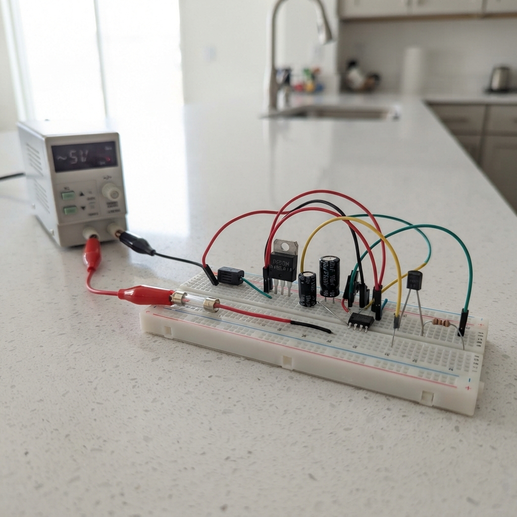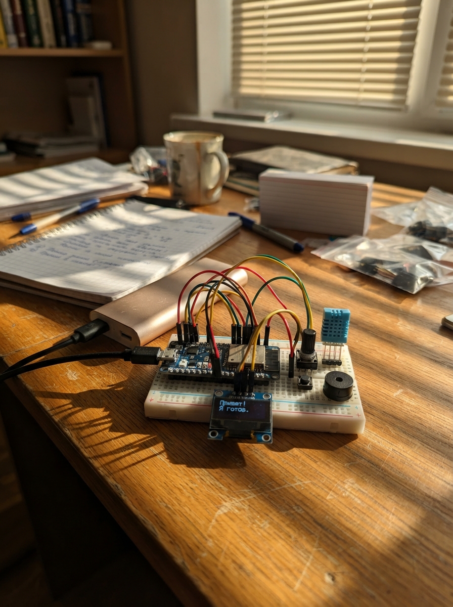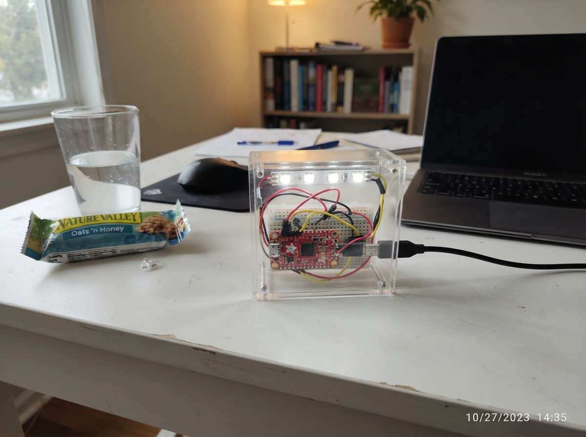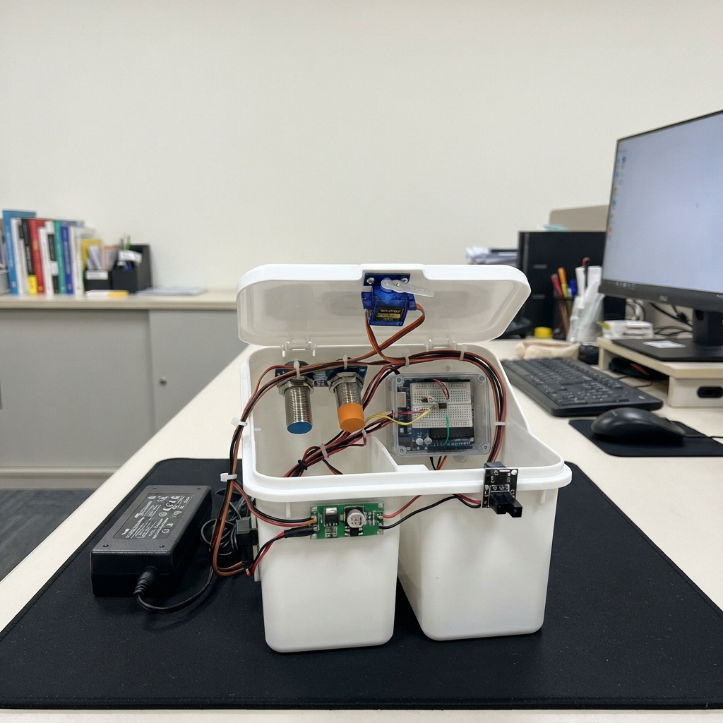
This smart waste sorting bin uses three sensor types to automatically route different materials into separate chutes. An ESP32 microcontroller reads an infrared obstacle sensor to detect items, an inductive sensor to identify metals, and a capacitive sensor to distinguish plastics from paper, then commands a servo motor to position a three-way chute accordingly.
Builders will receive a complete wiring diagram showing how to connect the sensors to the ESP32, integrate the servo motor with a separate 24V power supply via an optocoupler-protected circuit, and upload firmware that samples each material for 600ms before routing it to the correct bin. The guide includes assembly steps for constructing the lightweight chute mechanism and calibration instructions for reliable material detection.
Wiring diagram
Gather all the parts
Assemble it in 7 steps
1. Check the sensor types before wiring
This circuit is for a three-wire NPN normally-open LJ18A3-8-Z/BX metal sensor and LJC18A3-B-Z/BX capacitive switch. The supplied name LJV18A3-B-Z/BX was not verified; do not treat it as a confirmed interchangeable model. Brown is positive supply, blue is negative, black is the switching output for these chosen models.
- Do not use this wiring for PNP, normally-closed, AC, or two-wire sensors. Never connect a proximity sensor black wire directly to an ESP32 pin.
2. Set up the separate motor supply
With power disconnected, connect the enclosed adapter positive to buck VIN+ and negative to VIN-. Before connecting the servo, power the converter and use a multimeter to adjust VOUT+ to exactly 5.0V relative to VOUT-. Disconnect power again. Connect servo red to 5V output, brown to ground, and orange to GPIO18 (movement control). Connect the capacitor positive to servo 5V and negative striped lead to ground near the servo.
- Reversed capacitor polarity can cause rupture. Do not open the mains adapter. Do not connect buck output to ESP32 5V, VIN or 3V3. Use a converter rated for at least 1A continuous at 5V.
3. Wire the protected metal input
Metal sensor brown goes to adapter 12V and blue to ground. Connect 12V through limit_m (2.2k ohm) to opto_m anode (pin 1); cathode (pin 2) goes to sensor black. Opto emitter (pin 3) goes to ESP32 ground, collector (pin 4) to GPIO25 (metal signal). Connect pull_m (10k ohm) between collector and ESP32 3V3. Count pins from the package dot/notch using the PC817 datasheet.
4. Wire the protected capacitive input
Capacitive sensor brown goes to 12V, blue to ground. Connect 12V through limit_p (2.2k ohm) to opto_p pin 1; pin 2 goes to sensor black. Pin 3 goes to ESP32 ground, pin 4 to GPIO26 (capacitive signal). Connect pull_p (10k ohm) between pin 4 and 3V3. Join adapter negative, converter negative and ESP32 ground. These optical interfaces protect signals but shared grounds mean the whole project is not galvanically isolated.
5. Wire and adjust the object sensor
IR VCC goes to ESP32 3V3, GND to ground and OUT to GPIO27 (object present). Do not power this module from 5V. Adjust its knob so it sees your samples at the sensing station but not the empty chute.
6. Build a lightweight three-way chute
Use cardboard for three bins and a very light rotating chute supported by its own pivot, with the servo only turning it. Keep fingers away from the linkage. Test the unattached servo first, then fit its horn with the chute at the 90-degree middle position. Routes are paper sample at 30 degrees, plastic sample at 90 degrees and metal at 150 degrees. Change firmware angle constants if alignment needs adjustment; avoid hard stops. Do not make the servo lift a heavy lid or bin.
7. Calibrate and demonstrate one sample at a time
Position all three sensor faces at one small sensing station above the chute. Hold a sample a few millimetres from the proximity faces; verify metal detection with steel first. Keep mounting metal away from the sensing faces. Adjust capacitive sensitivity so your chosen plastic sample triggers but chosen dry paper does not. If both behave the same, this sensor cannot separate those samples. Firmware samples for 0.6 seconds, turns the chute, waits 0.8 seconds, then prints RELEASE over USB serial at 115200 baud. Hold the item until RELEASE, then drop it. Wait for Ready before the next item. The chute stays positioned until the IR path is clear for two seconds.
- This is a manually fed demonstration, not an unattended automatic sorter. Paper is the fallback label, not a measured material. Wet paper, glass, dark objects, foil and other plastics can be misclassified. Never feed sharp, hot, wet or hazardous waste.
Review all connections
1. Connections between "adapter" and "ESP32"
2. Connections between "buck" and "ESP32"
3. Connections between "servo" and "ESP32"
4. Connections between "cap" and "ESP32"
5. Connections between "ir" and "ESP32"
6. Connections between "metal" and "ESP32"
7. Connections between "limit_m" and "ESP32"
8. Connections between "opto_m" and "ESP32"
9. Connections between "pull_m" and "ESP32"
10. Connections between "plastic" and "ESP32"
11. Connections between "limit_p" and "ESP32"
12. Connections between "opto_p" and "ESP32"
13. Connections between "pull_p" and "ESP32"
Deploy the firmware
#include <Arduino.h>
#include <ESP32Servo.h>
constexpr int IR_PIN=27, METAL_PIN=25, CAP_PIN=26, SERVO_PIN=18;
constexpr int PAPER_ANGLE=30, PLASTIC_ANGLE=90, METAL_ANGLE=150;
Servo chute;
enum State {READY, SAMPLE, POSITION, WAIT_CLEAR, RETURNING};
State state=READY;
uint32_t since=0, clearSince=0, lastSample=0;
unsigned samples=0, metalHits=0, capHits=0;
int previous=-1;
void moveTo(int angle) { if(angle!=previous){chute.write(angle); previous=angle;} }
void setup(){
 Serial.begin(115200);
 pinMode(IR_PIN,INPUT_PULLUP); pinMode(METAL_PIN,INPUT); pinMode(CAP_PIN,INPUT);
 chute.setPeriodHertz(50); chute.attach(SERVO_PIN,1000,2000); moveTo(90);
 state=RETURNING; since=millis();
 Serial.println("DEMO ONLY: metal first; capacitive response=plastic sample; otherwise paper sample.");
 Serial.println("Hold ONE sample at all sensors. Wait for RELEASE before dropping into chute.");
}
void loop(){
 uint32_t now=millis();
 bool present=digitalRead(IR_PIN)==LOW;
 if(state==READY){
  if(present){state=SAMPLE; since=now; lastSample=now; samples=metalHits=capHits=0; Serial.println("Sampling: hold item still.");}
 }else if(state==SAMPLE){
  if(!present){state=READY; Serial.println("Item removed: cancelled.");}
  else if(now-lastSample>=10){
   lastSample=now; ++samples;
   metalHits += digitalRead(METAL_PIN)==LOW;
   capHits += digitalRead(CAP_PIN)==LOW;
   if(now-since>=600){
    if(metalHits*4>=samples){moveTo(METAL_ANGLE);Serial.println("METAL route");}
    else if(capHits*2>=samples){moveTo(PLASTIC_ANGLE);Serial.println("PLASTIC SAMPLE route (not verified material)");}
    else {moveTo(PAPER_ANGLE);Serial.println("PAPER SAMPLE route (not verified material)");}
    state=POSITION; since=now;
   }
  }
 }else if(state==POSITION){
  if(now-since>=800){state=WAIT_CLEAR; clearSince=0; Serial.println("RELEASE item into chute now.");}
 }else if(state==WAIT_CLEAR){
  if(present) clearSince=0;
  else if(clearSince==0) clearSince=now;
  else if(now-clearSince>=2000){moveTo(90);state=RETURNING;since=now;}
 }else if(state==RETURNING && now-since>=800){
  if(!present){state=READY;Serial.println("Ready for ONE item.");}
 }
 delay(2);
}
Remix this project
Make it yours in one click
Open a full copy of this project in your own Schematik workspace, diagram, code, parts, and assembly steps included. Swap the sensor, add features, or redesign the whole thing with AI. The author's original stays untouched.