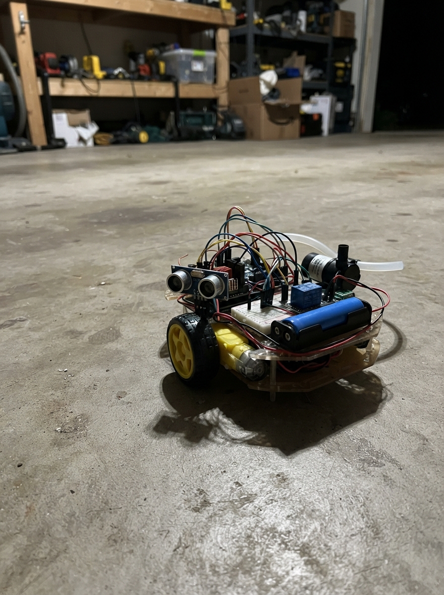
This automatic spray cleaning robot combines an ESP32 web controller with an Arduino Uno motion controller to create a WiFi-enabled cleaning platform. The robot uses ultrasonic distance sensors to navigate autonomously, dual DC motors for movement, and a 12V submersible pump triggered by a relay module to spray cleaning solution.
The guide provides a complete wiring diagram connecting the L298N motor driver, HC-SR04 sensors, relay module, and power distribution through buck converters. Builders will receive the full firmware for both the ESP32 (web server and command interface) and Arduino Uno (motor and sensor control), plus step-by-step assembly instructions covering battery pack configuration, power supply setup, and safe testing procedures before autonomous operation.
Wiring diagram
Gather all the parts
Assemble it in 8 steps
1. Keep the electronics dry
Mount the Arduino, ESP32 expansion board, L298N motor driver, MP1584 buck converter, relay, and pump where water cannot splash onto them. Keep the small MP1584 adjustment screw easy to reach.
- Water touching the boards can short the battery and damage the electronics.
2. Make the three-cell battery pack
Use a proper 3-cell 18650 holder or a ready-made 3S pack; do not solder directly to loose cells. Put cell_1, cell_2, and cell_3 in series: cell_1 positive to cell_2 negative, then cell_2 positive to cell_3 negative. The free cell_1 negative is the pack negative; the free cell_3 positive is the pack positive.
- Without a BMS, the cells have no protection against being drained too far, being overcharged, or a short circuit. Stop using the pack when its total voltage reaches 9.0 V, charge it only with a balanced 3S lithium charger, and disconnect it immediately if a cell or wire gets warm.
- A 3-cell lithium pack can deliver enough current to melt thin wires or start a fire during a short circuit. Add an inline fuse close to the pack positive before normal use.
3. Set the 5 V buck supply
With the battery disconnected from every other module, connect the pack positive to buck_5v VIN (input power) and pack negative to buck_5v GND (ground). Connect the battery briefly and use a meter to adjust VOUT to exactly 5.0 V. Disconnect the battery again after setting it.
- More than 5 V on the Arduino 5V pin, ESP32 5V/VIN pin, sensors, or relay can damage them.
4. Wire the Arduino and three distance sensors
Connect buck_5v VOUT to Arduino 5V (power) and buck_5v GND to Arduino GND (ground). For each sensor, connect VCC to the 5 V supply (power) and GND to the shared ground (ground). Front-left: TRIG to A0 (signal), ECHO to A1 (signal). Front: TRIG to A2 (signal), ECHO to A3 (signal). Front-right: TRIG to A4 (signal), ECHO to A5 (signal).
- Do not join any TRIG or ECHO wires together; each sensor needs its own two signal wires.
- Do not use the Arduino 3.3 V pin for these sensors.
5. Wire the ESP32 from the 5 V buck output
Do not use the expansion-board DC barrel jack. Connect esp32_wifi 5V/VIN to buck_5v VOUT (power) and ESP32 GND to the shared ground (ground). Connect ESP32 TX0/GPIO1 to Arduino D2 (Wi-Fi command signal). Connect Arduino D3 to the 1 kΩ resistor A end (signal); join the 1 kΩ resistor B end to ESP32 RX0/GPIO3 and the 2 kΩ resistor A end; connect the 2 kΩ resistor B end to shared ground. The two resistors reduce Arduino's 5 V reply signal to a safe ESP32 level.
- Keep the ESP32 USB socket reachable because it needs its own Wi-Fi controller firmware flashed separately from the Arduino.
- Never connect Arduino D3 directly to ESP32 RX0/GPIO3; the Arduino 5 V signal can damage the ESP32 input.
- Never connect the 3-cell battery directly to ESP32 5V/VIN or to its barrel jack in this version.
6. Wire the L298N wheel driver
Remove the small 5V-EN jumper from the L298N. Connect buck_5v VOUT to L298N 5V (logic power), buck_5v GND to L298N GND (ground), and pack positive to L298N 12V (motor power). Leave ENA and ENB jumpers fitted. Connect IN1 to Arduino D6 (left wheel direction), IN2 to D9 (left wheel direction), IN3 to D11 (right wheel direction), and IN4 to D10 (right wheel direction). Connect the left motor to OUT1 and OUT2; connect the right motor to OUT3 and OUT4.
- If one wheel turns the wrong way, disconnect the battery and swap only that motor's two wires.
- Keep the battery disconnected while tightening terminals; a loose copper strand can short the battery.
7. Wire the pump relay
Connect relay VCC to buck_5v VOUT (power), relay GND to the shared ground (ground), and relay IN to Arduino D4 (control). Connect pack positive to relay COM (pump power), relay NO to pump PUMP+ (switched power), and pump PUMP- to pack negative/shared ground (ground).
- Never connect the pump directly to an Arduino pin.
- The relay is the pump switch; the 3-cell battery wires must stay on COM, NO, and the pump power wires only.
8. Test safely before driving
Raise both wheels off the floor and keep the pump inlet in water before a long test. Plug the Arduino into USB and press Deploy, then connect the battery briefly. In automatic mode the pump runs for 5 seconds and rests for 5 seconds. The ESP32 commands are A for automatic mode; F, B, L, R for manual movement; S to stop; and P to switch the pump state.
- Disconnect the battery immediately if any battery cell, wire, buck converter, relay, L298N, ESP32, or Arduino gets warm.
- Do not charge the three loose series cells through the MP1584; it is not a lithium battery charger.
Review all connections
1. Connections between "cell_1" and "ESP32"
2. Connections between "cell_2" and "ESP32"
3. Connections between "cell_3" and "ESP32"
4. Connections between "buck_5v" and "ESP32"
5. Connections between "sonar_front" and "ESP32"
6. Connections between "sonar_left" and "ESP32"
7. Connections between "sonar_right" and "ESP32"
8. Connections between "pump_relay" and "ESP32"
9. Connections between "pump" and "ESP32"
10. Connections between "motor_driver" and "ESP32"
11. Connections between "uart_divider_top" and "ESP32"
12. Connections between "uart_divider_bottom" and "ESP32"
13. Connections between "arduino_uno_controller" and "ESP32"
Deploy the firmware
#include <Arduino.h>
#include <WiFi.h>
#include <WebServer.h>
#include <ctype.h>

// ESP32 TXD/GPIO1 -> Arduino Uno D2
// Arduino Uno D3 -> 1k resistor -> ESP32 RXD/GPIO3
// ESP32 RXD/GPIO3 -> 2k resistor -> GND
const int UNO_COMMAND_TX_PIN = 1;
const int UNO_STATUS_RX_PIN = 3;
const char *AP_NAME = "MopBot";
const char *AP_PASSWORD = "MopBot123";

WebServer server(80);
String unoStatus = "Waiting for Arduino";
String lastCommand = "None";

void readUnoStatus() {
  static String line;
  while (Serial.available()) {
    char c = (char)Serial.read();
    if (c == '\r') continue;
    if (c == '\n') {
      if (line.length()) { unoStatus = line; line = ""; }
    } else if (c >= 32 && c <= 126 && line.length() < 40) {
      line += c;
    }
  }
}

void sendCommand(char c) {
  Serial.write(c);
  Serial.flush();
  lastCommand = String(c);
}

String json() {
  return String("{\"status\":\"") + unoStatus + "\",\"last\":\"" + lastCommand + "\"}";
}

const char PAGE[] PROGMEM = R"HTML(
<!doctype html><html><head><meta name="viewport" content="width=device-width,initial-scale=1"><title>Mop Bot</title><style>body{margin:0;padding:20px;text-align:center;background:#0f172a;color:#fff;font-family:Arial}.box{max-width:380px;margin:12px auto;padding:12px;background:#1e293b;border-radius:14px}.grid{display:grid;grid-template-columns:95px 95px 95px;grid-template-rows:76px 76px 76px;justify-content:center;gap:11px;margin:20px auto}button{border:0;border-radius:14px;color:white;background:#2563eb;font-size:16px;font-weight:bold;touch-action:manipulation;box-shadow:0 4px #1d4ed8}.stop{background:#dc2626;box-shadow:0 4px #991b1b}.auto{background:#059669;box-shadow:0 4px #047857}.pump{background:#9333ea;box-shadow:0 4px #6b21a8}.wide{width:300px;height:58px;margin:7px}.v{color:#5eead4;font-weight:bold}</style></head><body><h1>Mop Bot</h1><div class="box">Arduino: <span class="v" id="s">Loading...</span><br>Last: <span class="v" id="l">None</span></div><div class="grid"><i></i><button class="move" data-c="F">▲<br>Forward</button><i></i><button class="move" data-c="L">◀<br>Left</button><button class="stop" onclick="cmd('S')">■<br>STOP</button><button class="move" data-c="R">▶<br>Right</button><i></i><button class="move" data-c="B">▼<br>Back</button><i></i></div><button class="auto wide" onclick="cmd('A')">AUTO MODE</button><br><button class="pump wide" onclick="cmd('P')">PUMP ON / OFF</button><p>Hold a direction button to move. Releasing it stops the robot.</p><script>let t=null;function show(x){s.textContent=x.status;l.textContent=x.last}function cmd(c){fetch('/command?c='+c).then(x=>x.json()).then(show).catch(()=>s.textContent='Command failed')}function begin(c){cmd(c);clearInterval(t);t=setInterval(()=>cmd(c),250)}function end(){clearInterval(t);t=null;cmd('S')}document.querySelectorAll('.move').forEach(b=>{let c=b.dataset.c;b.onpointerdown=e=>{e.preventDefault();begin(c)};b.onpointerup=e=>{e.preventDefault();end()};b.onpointerleave=end;b.onpointercancel=end});onblur=end;setInterval(()=>fetch('/status').then(x=>x.json()).then(show).catch(()=>{}),1000)</script></body></html>
)HTML";

void home() { server.send_P(200, "text/html", PAGE); }
void status() { server.send(200, "application/json", json()); }
void command() {
  if (!server.hasArg("c") || server.arg("c").length() != 1) { server.send(400, "application/json", "{\"error\":\"Missing command\"}"); return; }
  char c = toupper(server.arg("c")[0]);
  if (String("AFBLRSP").indexOf(c) < 0) { server.send(400, "application/json", "{\"error\":\"Invalid command\"}"); return; }
  sendCommand(c);
  status();
}

void setup() {
  Serial.begin(9600, SERIAL_8N1, UNO_STATUS_RX_PIN, UNO_COMMAND_TX_PIN);
  WiFi.mode(WIFI_AP);
  WiFi.softAP(AP_NAME, AP_PASSWORD);
  server.on("/", home);
  server.on("/command", command);
  server.on("/status", status);
  server.begin();
}

void loop() {
  server.handleClient();
  readUnoStatus();
  delay(2);
}
Remix this project
Make it yours in one click
Open a full copy of this project in your own Schematik workspace, diagram, code, parts, and assembly steps included. Swap the sensor, add features, or redesign the whole thing with AI. The author's original stays untouched.