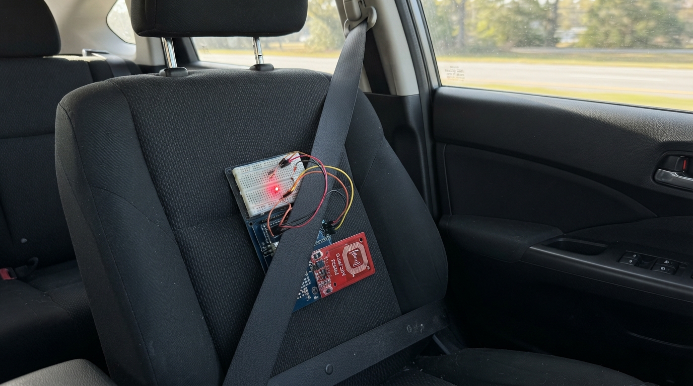
This project builds an RFID tag reader using an ESP32 microcontroller and a PN532 NFC module communicating over I2C. The reader detects NFC tags and cards within range, displays the unique identifier (UID) on the serial monitor, and provides visual feedback through green and red LEDs.
The guide includes a complete wiring diagram showing how to connect the PN532 module to the ESP32's I2C pins, a full parts list, step-by-step assembly instructions, and ready-to-upload firmware. By the end, the reader will scan your own NFC tags and report their UIDs, making it a foundation for access control, inventory tracking, or interactive projects.
Wiring diagram
Gather all the parts
Assemble it in 7 steps
1. Set the PN532 reader to I²C mode
With the ESP32 unplugged, find the two small mode switches on your PN532 board. Set both switches to ON for I²C mode; this is the setting that lets the reader use the two data wires below.
- Check the switch labels printed on the board; the PN532 reader’s manual calls this I²C mode.
- Do not change these switches while the board is powered, because an accidental short can damage the reader.
2. Place the parts without power
Put the ESP32 DevKit v1, PN532 reader, two 220 Ω resistors, and the red and green LEDs on a breadboard. Keep the PN532 antenna facing upward and leave the ESP32 unplugged while making connections.
- The LED’s long leg is the positive leg; the short leg and flat edge are the negative side.
3. Connect power to the NFC reader
Connect PN532 VCC to the ESP32 3V3 pin (power), and connect PN532 GND to an ESP32 GND pin (ground).
- These wires give both boards the same voltage reference.
- Do not connect PN532 VCC to 5 V; this project uses the ESP32’s 3.3 V pin, and swapped power wires can damage the reader.
4. Connect the two reader data wires
Connect PN532 SDA to ESP32 GPIO21 (data), and PN532 SCL to ESP32 GPIO22 (clock). Leave the optional PN532 IRQ and RSTO pins unconnected.
- Follow the small SDA and SCL labels printed next to the PN532 header pins; a wire in the wrong breadboard row stops the reader from responding.
5. Add the green scan light
Connect ESP32 GPIO25 to one leg of green_resistor (signal), connect its other leg to the long leg of green_led (current limiting), then connect the short leg of green_led to ESP32 GND (ground).
- The resistor can face either direction; it prevents too much current from damaging the LED.
6. Add the red warning light
Connect ESP32 GPIO26 to one leg of red_resistor (signal), connect its other leg to the long leg of red_led (current limiting), then connect the short leg of red_led to ESP32 GND (ground).
- Keep each LED’s long leg in a separate breadboard row so the two lights cannot touch.
7. Test with your own NFC tag
Hold an NFC tag, card, or phone tag you own flat against the PN532 antenna. When it is detected, the green LED flashes and its ID is printed over USB.
- The tag reads best within a few centimetres with its flat face parallel to the antenna.
- Use this project only with tags and systems you own or are authorised to test.
Review all connections
1. Connections between "green_resistor" and "ESP32"
2. Connections between "green_led" and "ESP32"
3. Connections between "red_resistor" and "ESP32"
4. Connections between "red_led" and "ESP32"
5. Connections between "pn532_reader" and "ESP32"
Deploy the firmware
#include <Arduino.h>
#include <Wire.h>
#include <Adafruit_PN532.h>

constexpr uint8_t PN532_SDA_PIN = 21;
constexpr uint8_t PN532_SCL_PIN = 22;
constexpr uint8_t GREEN_LED_PIN = 25;
constexpr uint8_t RED_LED_PIN = 26;

// I2C mode does not need the optional IRQ or reset wires.
Adafruit_PN532 nfc(-1, -1, &Wire);

void flashLed(uint8_t pin, uint16_t durationMs) {
  digitalWrite(pin, HIGH);
  delay(durationMs);
  digitalWrite(pin, LOW);
}

void printUid(const uint8_t *uid, uint8_t uidLength) {
  Serial.print("NFC UID: ");
  for (uint8_t i = 0; i < uidLength; ++i) {
    if (uid[i] < 0x10) {
      Serial.print('0');
    }
    Serial.print(uid[i], HEX);
    if (i + 1 < uidLength) {
      Serial.print(':');
    }
  }
  Serial.println();
}

void setup() {
  Serial.begin(115200);
  pinMode(GREEN_LED_PIN, OUTPUT);
  pinMode(RED_LED_PIN, OUTPUT);
  digitalWrite(GREEN_LED_PIN, LOW);
  digitalWrite(RED_LED_PIN, LOW);

  Wire.begin(PN532_SDA_PIN, PN532_SCL_PIN);
  nfc.begin();

  uint32_t version = nfc.getFirmwareVersion();
  if (version == 0) {
    Serial.println("PN532 not found. Check power, SDA/SCL wires, and set both PN532 switches to I2C mode.");
    flashLed(RED_LED_PIN, 500);
    return;
  }

  nfc.SAMConfig();
  Serial.println("PN532 ready. Hold an NFC tag or card you own near the antenna.");
  flashLed(GREEN_LED_PIN, 120);
}

void loop() {
  uint8_t uid[7] = {0};
  uint8_t uidLength = 0;
  bool tagFound = nfc.readPassiveTargetID(PN532_MIFARE_ISO14443A, uid, &uidLength, 100);

  if (!tagFound) {
    delay(20);
    return;
  }

  printUid(uid, uidLength);
  flashLed(GREEN_LED_PIN, 180);
  delay(250);
}
Remix this project
Make it yours in one click
Open a full copy of this project in your own Schematik workspace, diagram, code, parts, and assembly steps included. Swap the sensor, add features, or redesign the whole thing with AI. The author's original stays untouched.