Schematik build
How to Build One ESP32 Split-Flap Clock Digit
A 3D-printed mechanical digit with stepper motion and magnetic homing
What you'll build
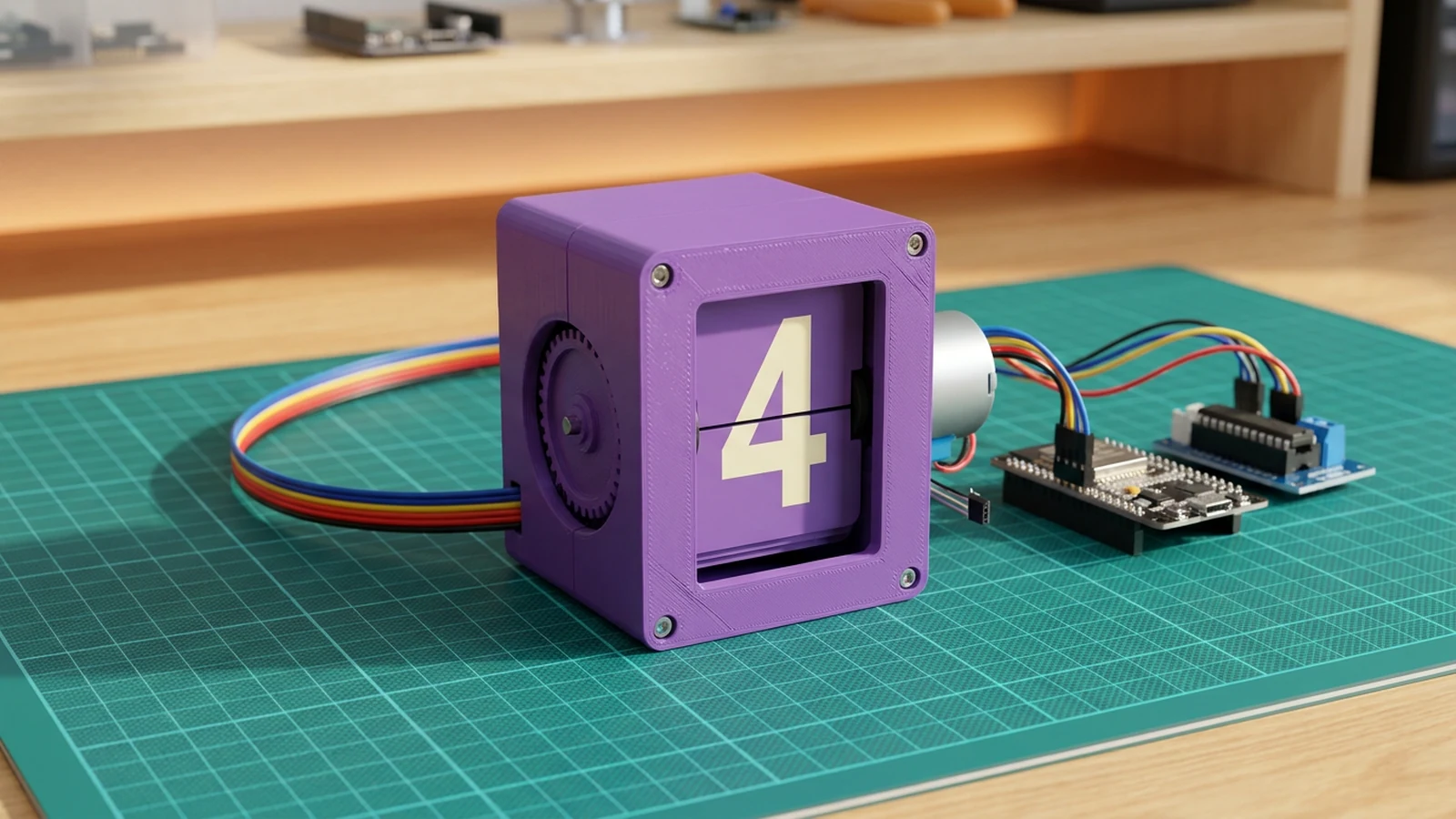
Build one working split-flap digit module: the mechanical unit that flips through numbers in a retro clock. The electronics are deliberately simple: an ESP32 sends four step signals to a ULN2003 driver, the driver moves a 28BYJ-48 geared stepper, and a Honeywell SS49E Hall sensor plus a small magnet gives the wheel a repeatable home position after boot.
Keep the first build to one digit. A split-flap clock only feels simple once one module can home reliably, move exactly one flap at a time, and recover after power loss. After that, duplicating the digit is mostly more drivers, more Hall inputs, and a clean power layout.
Watch the original build inspiration here on YouTube.
What you are building
This guide covers one numeric digit, not a complete multi-digit clock. The module has four jobs:
- spin the 28BYJ-48 through a ULN2003 driver,
- detect a known zero position with a magnet and Hall sensor,
- advance by a calibrated number of steps per flap,
- expose Serial Monitor commands so you can test digits before scaling up.
That boundary is intentional. If one digit misses steps, rubs mechanically, or homes unreliably, a four-digit clock will multiply the problem.
Upload and calibrate
The sketch uses Arduino's built-in Stepper library, so no third-party motor library is required. Flash it and open Serial Monitor at 115200 baud.
Useful commands:
?prints available commands.rprints the current Hall sensor reading.hhomes the wheel using the magnet.0–9moves directly to a digit.nadvances to the next digit.dtoggles demo mode; manual digit commands automatically pause the demo cycle.
Start by sending r with the magnet away from the sensor, then again with the magnet near the sensor. Set HOME_THRESHOLD between those two readings. With the source model's magnet orientation, the original V1 sketch homes when the 49E reading rises above its threshold, so this firmware uses the same direction. If your measured near reading is lower, flip the comparison inside magnetDetected() rather than guessing.
After homing works, send 0 through 9. The source V1 drum has 40 positions and its own sketch uses integer division of 2048 steps by 40 characters, so this firmware starts at 51 steps per flap and maps digits to source positions 27–36. If movement accumulates error over a complete revolution, fix mechanical drag first, then calibrate the effective step count without changing the 40-position mapping.
Troubleshooting
- Motor buzzes but does not turn: check 5 V motor power, shared ground, and the coil order. The sketch uses
IN1, IN3, IN2, IN4, which matches many 28BYJ-48 + ULN2003 kits. - ESP32 resets during a move: use a separate 5 V supply for the motor and keep grounds common.
- Homing never finishes: print the Hall reading with
r, reduce the magnet gap, and tuneHOME_THRESHOLD. - Digit lands between flaps: adjust
STEPS_PER_FLAP, then test a full 0-9 cycle. - One flap works but later flaps drift: fix mechanical drag first, then lower speed or acceleration.
Scaling to a full clock
Once one digit is reliable, duplicate the motor driver and Hall sensor per digit. Keep motor power separate from ESP32 logic power, share grounds, and avoid reusing GPIO 34 for every Hall sensor; each digit needs its own input. A full clock also needs timekeeping logic, but the mechanical calibration should stay per digit.
Wiring diagram
Gather all the parts
Assemble it in 5 steps
1.
2.
3.
4.
5.
Review all connections
1. Connections between "28byj-48-stepper-1" and "ESP32"
2. Connections between "ky-035-hall-sensor-1" and "ESP32"
3. Connections between "uln2003-stepper-driver-1" and "ESP32"
Deploy the firmware
#include <Arduino.h>
#include <Stepper.h>

#define STEPS_PER_REV 2048
#define MOTOR_IN1 16
#define MOTOR_IN2 17
#define MOTOR_IN3 18
#define MOTOR_IN4 19
#define HALL_PIN 34
#define HOME_THRESHOLD 2600
#define FLAP_COUNT 40
#define FIRST_DIGIT_FLAP 27
#define STEPS_PER_FLAP (STEPS_PER_REV / FLAP_COUNT)

Stepper flapMotor(STEPS_PER_REV, MOTOR_IN1, MOTOR_IN3, MOTOR_IN2, MOTOR_IN4);
int currentFlap = 0;
int currentDigit = -1;
bool demoMode = false;
unsigned long lastDemoStep = 0;

bool magnetDetected() { return analogRead(HALL_PIN) > HOME_THRESHOLD; }
void stepForward(int steps) { flapMotor.step(-steps); }
void homeWheel() {
  Serial.println("Homing split-flap wheel...");
  for (int i = 0; i < STEPS_PER_REV + 300; i += 4) {
    if (magnetDetected()) {
      stepForward(5);
      currentFlap = 0;
      currentDigit = -1;
      Serial.println("Home magnet found at blank flap");
      return;
    }
    stepForward(4);
  }
  Serial.println("Home magnet not found. Check sensor alignment.");
}
void moveToFlap(int targetFlap) {
  targetFlap = constrain(targetFlap, 0, FLAP_COUNT - 1);
  if (targetFlap < currentFlap) homeWheel();
  stepForward((targetFlap - currentFlap) * STEPS_PER_FLAP);
  currentFlap = targetFlap;
}
void showDigit(int targetDigit) {
  targetDigit = constrain(targetDigit, 0, 9);
  moveToFlap(FIRST_DIGIT_FLAP + targetDigit);
  currentDigit = targetDigit;
  Serial.printf("Showing digit %d on source flap %d\n", currentDigit, currentFlap);
}
void printHelp() { Serial.println("Commands: ? help, r Hall reading, h home, 0-9 digit, n next, d demo"); }
void handleCommand(char command) {
  if (command >= '0' && command <= '9') { demoMode = false; showDigit(command - '0'); return; }
  switch (command) {
    case '?': printHelp(); break;
    case 'r': Serial.printf("Hall reading: %d\n", analogRead(HALL_PIN)); break;
    case 'h': demoMode = false; homeWheel(); break;
    case 'n': demoMode = false; showDigit(currentDigit < 0 ? 0 : (currentDigit + 1) % 10); break;
    case 'd': demoMode = !demoMode; lastDemoStep = millis(); Serial.printf("Demo %s\n", demoMode ? "on" : "off"); break;
    case '\n': case '\r': break;
    default: Serial.println("Unknown command. Send ? for help.");
  }
}
void setup() {
  Serial.begin(115200); analogReadResolution(12); pinMode(HALL_PIN, INPUT); flapMotor.setSpeed(12); delay(500); homeWheel(); printHelp();
}
void loop() {
  while (Serial.available()) handleCommand((char)Serial.read());
  if (demoMode && millis() - lastDemoStep >= 1200) { showDigit(currentDigit < 0 ? 0 : (currentDigit + 1) % 10); lastDemoStep = millis(); }
}
Remix this project
Make it yours in one click
Open a full copy of this project in your own Schematik workspace — diagram, code, parts, and assembly steps included. Swap the sensor, add features, or redesign the whole thing with AI. The author's original stays untouched.
Related projects
How to Build an ESP32 Pomodoro Focus Timer
ESP32 · Beginner · 45 minutes · July 22, 2026Schematik
How to Build an ESP32 Weather Station with Clothing Advice
ESP32 · Intermediate · 30 minutes · June 12, 2026Schematik
E-Ink Photo Camera
ESP32 · Intermediate · 2 hours · August 24, 2026Schematik