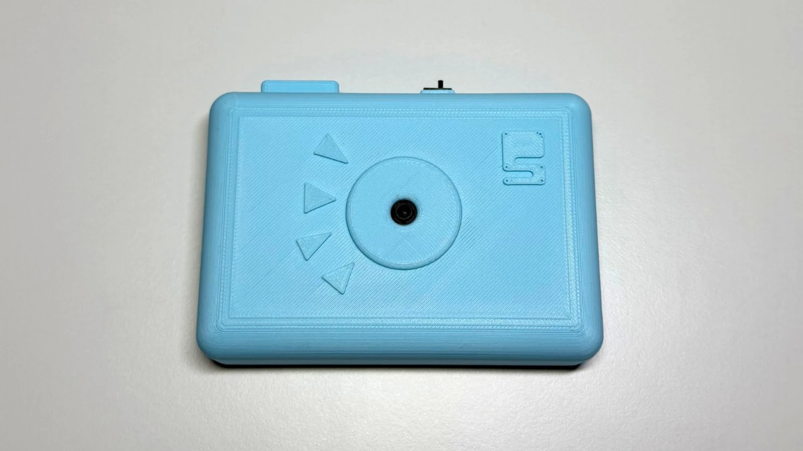
Schematik build
E-Ink Photo Camera
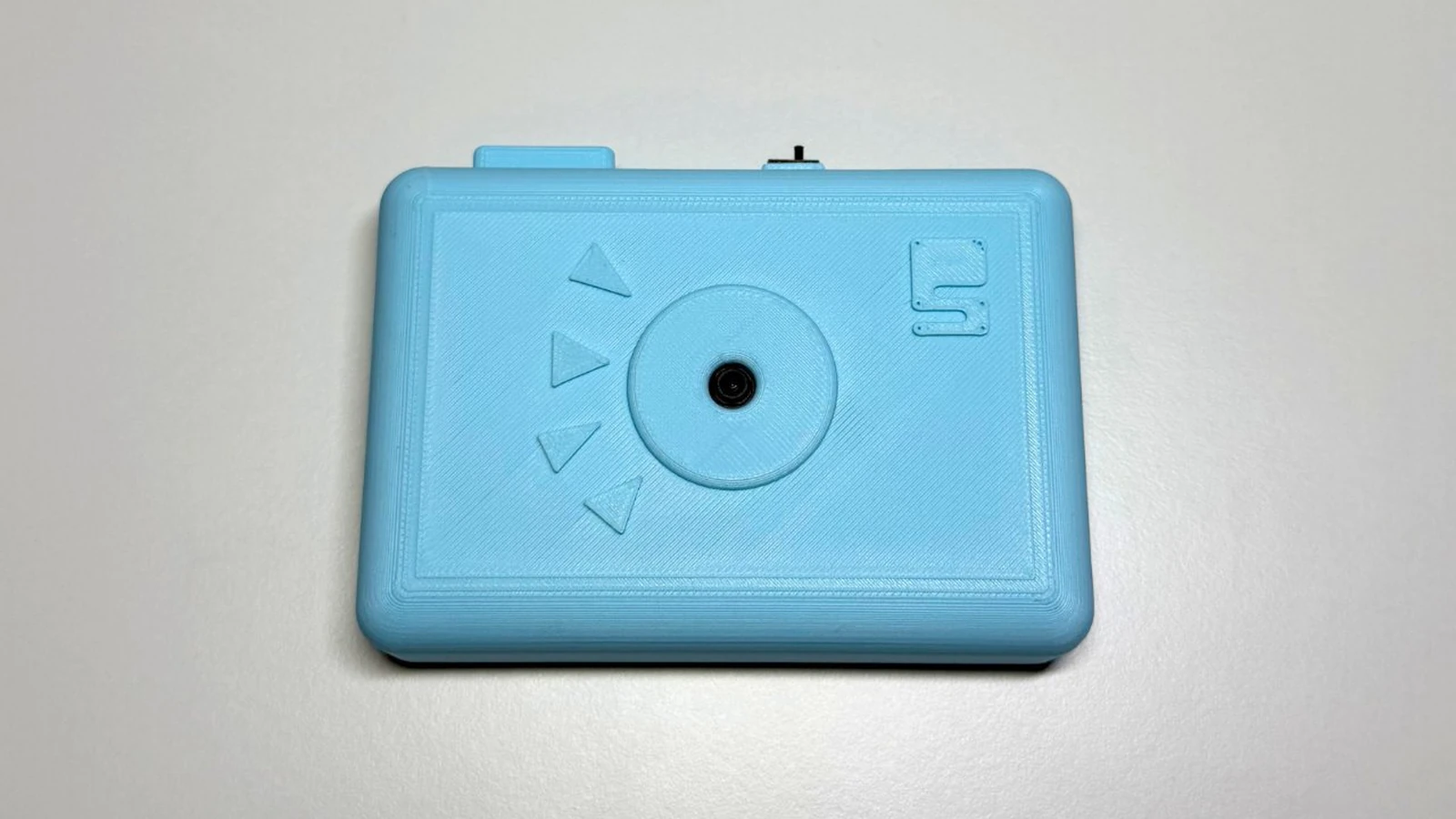
This project pairs a Seeed Studio XIAO ESP32S3 Sense camera with an M5Paper e-ink display to create a wireless photo capture system. The camera module captures JPEG images and transmits them over ESP-NOW to the M5Paper, where they're displayed on the e-ink screen. A simple toggle switch controls power to keep the compact 400mAh battery running efficiently.
Builders will receive a complete wiring diagram showing battery connections with the power switch, the camera module pinout for the XIAO ESP32S3, and step-by-step assembly instructions. The guide includes firmware for both the camera and receiver, along with a parts list and details on configuring the ESP-NOW wireless protocol for reliable image transmission.
Wiring diagram

Gather all the parts
Assemble it in 4 steps
1. Prepare the XIAO camera
With power disconnected, fit the OV3660 camera expansion board to the Seeed Studio XIAO ESP32S3 Sense in its correct keyed orientation. These camera-interface pins are already dedicated to the camera, so do not connect other wires to them.
- Keep the camera lens clean and unobstructed.
- Disconnect both USB and the LiPo before fitting or removing the camera board.
2. Put the power switch in the positive battery wire
With USB unplugged, connect lipo_400mah BAT+ (the red, positive wire) to power_switch COM, the center terminal. Connect power_switch NO1, one outer terminal, to the XIAO BAT+ battery pad or connector positive contact. Leave power_switch NO2, the other outer terminal, unconnected. The switch joins COM to NO1 in its chosen on position, sending battery power to the XIAO.
- Before mounting the switch in the case, use its lever position to decide which direction should mean on.
- If the switch works in the opposite direction from your label, move the XIAO BAT+ wire from NO1 to NO2 instead.
- Do not connect the battery's positive wire to both outer switch terminals — that would bypass the switch and leave the camera powered all the time.
- Make sure BAT+ and BAT− are not swapped — reversed battery power can damage the XIAO.
3. Connect and secure the battery negative wire
Connect lipo_400mah BAT− (the black, negative wire) directly to the XIAO BAT− battery pad or connector negative contact. Secure the LiPo, switch, and wires so they cannot be pinched, pulled, or touch each other.
- Use heat-shrink tubing or electrical tape over exposed solder joints.
- Never reverse, short, crush, puncture, or leave a LiPo charging unattended. Charge through the XIAO USB-C port only.
4. Trigger photos from the M5Paper
Deploy the camera firmware with Schematik and deploy the separate M5Paper receiver firmware. Switch the XIAO on, keep both devices within normal indoor radio range, then press the designated on-screen or physical button on the M5Paper. It sends an ESP-NOW capture request; the XIAO takes a QVGA JPEG and returns it for the M5Paper to show.
- Both firmwares use ESP-NOW Wi-Fi channel 1; do not join either device to a normal Wi-Fi network while using this build.
- There is no wire between the M5Paper and XIAO in this design. They communicate by radio.
Review all connections
1. Connections between "lipo_400mah" and "ESP32"
2. Connections between "power_switch" and "ESP32"
Deploy the firmware
#include <Arduino.h>
#include <WiFi.h>
#include <esp_now.h>
#include <esp_wifi.h>
#include "esp_camera.h"

// Seeed Studio XIAO ESP32S3 Sense camera expansion board (OV3660).
#define PWDN_GPIO_NUM     -1
#define RESET_GPIO_NUM    -1
#define XCLK_GPIO_NUM     10
#define SIOD_GPIO_NUM     40
#define SIOC_GPIO_NUM     39
#define Y9_GPIO_NUM       48
#define Y8_GPIO_NUM       11
#define Y7_GPIO_NUM       12
#define Y6_GPIO_NUM       14
#define Y5_GPIO_NUM       16
#define Y4_GPIO_NUM       18
#define Y3_GPIO_NUM       17
#define Y2_GPIO_NUM       15
#define VSYNC_GPIO_NUM    38
#define HREF_GPIO_NUM     47
#define PCLK_GPIO_NUM     13

// The M5Paper receiver sketch must use this same ESP-NOW channel.

static constexpr size_t JPEG_CHUNK_BYTES = 232;

enum PacketType : uint8_t {
  PACKET_CAPTURE_REQUEST = 1,
  PACKET_IMAGE_START = 2,
  PACKET_IMAGE_DATA = 3,
  PACKET_IMAGE_END = 4,
  PACKET_ERROR = 5
};

struct __attribute__((packed)) CameraPacket {
  uint32_t magic;
  uint8_t type;
  uint16_t sequence;
  uint16_t dataLength;
  uint32_t imageLength;
  uint16_t width;
  uint16_t height;
  uint8_t data[JPEG_CHUNK_BYTES];
};

// Forward declarations
bool preparePeer(const uint8_t *mac);
void sendError(const char *message);
void sendCapturedPhoto();
void onEspNowReceive(const esp_now_recv_info_t *info, const uint8_t *incomingData, int length);
void configureCamera();

static constexpr uint8_t ESPNOW_CHANNEL = 1;
static constexpr uint32_t PACKET_MAGIC = 0x5043414DUL; // "PCAM"

static_assert(sizeof(CameraPacket) <= ESP_NOW_MAX_DATA_LEN, "ESP-NOW packet is too large");

volatile bool captureRequested = false;
uint8_t requesterMac[6] = {0};
bool requesterKnown = false;

bool preparePeer(const uint8_t *mac) {
  if (esp_now_is_peer_exist(mac)) {
    return true;
  }

  esp_now_peer_info_t peer = {};
  memcpy(peer.peer_addr, mac, 6);
  peer.channel = ESPNOW_CHANNEL;
  peer.encrypt = false;
  return esp_now_add_peer(&peer) == ESP_OK;
}

void sendError(const char *message) {
  if (!requesterKnown || !preparePeer(requesterMac)) {
    return;
  }

  CameraPacket packet = {};
  packet.magic = PACKET_MAGIC;
  packet.type = PACKET_ERROR;
  packet.dataLength = min(strlen(message), JPEG_CHUNK_BYTES);
  memcpy(packet.data, message, packet.dataLength);
  esp_now_send(requesterMac, reinterpret_cast<const uint8_t *>(&packet),
               offsetof(CameraPacket, data) + packet.dataLength);
}

void sendCapturedPhoto() {
  if (!requesterKnown || !preparePeer(requesterMac)) {
    return;
  }

  camera_fb_t *frame = esp_camera_fb_get();
  if (frame == nullptr) {
    sendError("Camera capture failed");
    return;
  }

  CameraPacket packet = {};
  packet.magic = PACKET_MAGIC;
  packet.type = PACKET_IMAGE_START;
  packet.imageLength = frame->len;
  packet.width = frame->width;
  packet.height = frame->height;
  if (esp_now_send(requesterMac, reinterpret_cast<const uint8_t *>(&packet),
                   offsetof(CameraPacket, data)) != ESP_OK) {
    esp_camera_fb_return(frame);
    return;
  }
  delay(12);

  uint16_t sequence = 0;
  for (size_t offset = 0; offset < frame->len; offset += JPEG_CHUNK_BYTES) {
    const size_t chunkLength = min(JPEG_CHUNK_BYTES, frame->len - offset);
    memset(&packet, 0, sizeof(packet));
    packet.magic = PACKET_MAGIC;
    packet.type = PACKET_IMAGE_DATA;
    packet.sequence = sequence++;
    packet.dataLength = chunkLength;
    memcpy(packet.data, frame->buf + offset, chunkLength);

    // A short gap prevents overflowing the ESP-NOW transmit queue.
    if (esp_now_send(requesterMac, reinterpret_cast<const uint8_t *>(&packet),
                     offsetof(CameraPacket, data) + chunkLength) != ESP_OK) {
      esp_camera_fb_return(frame);
      sendError("Radio transfer failed");
      return;
    }
    delay(4);
  }

  memset(&packet, 0, sizeof(packet));
  packet.magic = PACKET_MAGIC;
  packet.type = PACKET_IMAGE_END;
  packet.sequence = sequence;
  esp_now_send(requesterMac, reinterpret_cast<const uint8_t *>(&packet),
               offsetof(CameraPacket, data));
  esp_camera_fb_return(frame);
}

void onEspNowReceive(const esp_now_recv_info_t *info, const uint8_t *incomingData, int length) {
  if (length < static_cast<int>(offsetof(CameraPacket, data))) {
    return;
  }

  CameraPacket request = {};
  memcpy(&request, incomingData, min(length, static_cast<int>(sizeof(request))));
  if (request.magic != PACKET_MAGIC || request.type != PACKET_CAPTURE_REQUEST) {
    return;
  }

  memcpy(requesterMac, info->src_addr, sizeof(requesterMac));
  requesterKnown = true;
  captureRequested = true;
}

void configureCamera() {
  camera_config_t config = {};
  config.ledc_channel = LEDC_CHANNEL_0;
  config.ledc_timer = LEDC_TIMER_0;
  config.pin_d0 = Y2_GPIO_NUM;
  config.pin_d1 = Y3_GPIO_NUM;
  config.pin_d2 = Y4_GPIO_NUM;
  config.pin_d3 = Y5_GPIO_NUM;
  config.pin_d4 = Y6_GPIO_NUM;
  config.pin_d5 = Y7_GPIO_NUM;
  config.pin_d6 = Y8_GPIO_NUM;
  config.pin_d7 = Y9_GPIO_NUM;
  config.pin_xclk = XCLK_GPIO_NUM;
  config.pin_pclk = PCLK_GPIO_NUM;
  config.pin_vsync = VSYNC_GPIO_NUM;
  config.pin_href = HREF_GPIO_NUM;
  config.pin_sccb_sda = SIOD_GPIO_NUM;
  config.pin_sccb_scl = SIOC_GPIO_NUM;
  config.pin_pwdn = PWDN_GPIO_NUM;
  config.pin_reset = RESET_GPIO_NUM;
  config.xclk_freq_hz = 20000000;
  config.pixel_format = PIXFORMAT_JPEG;
  config.frame_size = FRAMESIZE_QVGA;
  config.jpeg_quality = 18;
  config.fb_count = 1;
  config.grab_mode = CAMERA_GRAB_WHEN_EMPTY;
  config.fb_location = CAMERA_FB_IN_PSRAM;

  if (esp_camera_init(&config) != ESP_OK) {
    while (true) {
      delay(1000);
    }
  }
}

void setup() {
  Serial.begin(115200);
  configureCamera();

  WiFi.mode(WIFI_STA);
  esp_wifi_set_channel(ESPNOW_CHANNEL, WIFI_SECOND_CHAN_NONE);
  if (esp_now_init() != ESP_OK) {
    while (true) {
      delay(1000);
    }
  }
  esp_now_register_recv_cb(onEspNowReceive);
}

void loop() {
  if (captureRequested) {
    captureRequested = false;
    sendCapturedPhoto();
  }
  delay(2);
}
Download project files
Remix this project
Make it yours in one click
Open a full copy of this project in your own Schematik workspace — diagram, code, parts, and assembly steps included. Swap the sensor, add features, or redesign the whole thing with AI. The author's original stays untouched.
Related projects
How to Build an ESP32-CAM Setup Portal Security Camera
ESP32 · Intermediate · 35 minutes · July 22, 2026Schematik
How to Build an ESP32 Video Doorbell
ESP32 · Intermediate · 45 minutes · July 22, 2026Schematik
Portable RGB Animation Display
ESP32 · Intermediate · 90 minutes · July 26, 2026Schematik