Schematik build
How to Build an ESP32 Pomodoro Focus Timer
OLED countdown, rotary controls, buzzer alerts, and LED progress
What you'll build
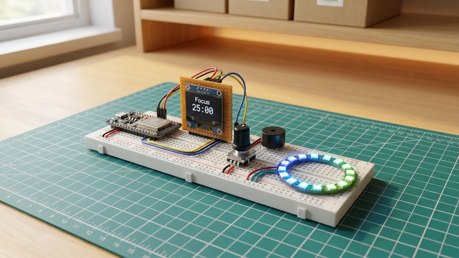
This guide walks through a desk-sized ESP32 focus timer for Pomodoro-style work sessions. The OLED shows the current mode and countdown, the rotary encoder gives you one physical control for start, pause, and reset, the buzzer gives short alerts at session transitions, and the LED ring shows progress at a glance without you having to look at the screen.
The build uses common parts: an ESP32 development board, SSD1306 I²C OLED, KY-040 rotary encoder, piezo buzzer, and a 16-pixel WS2812B ring. The starter code keeps the behaviour intentionally simple: 25 minutes of focus, 5 minutes of break, pause and resume from the encoder button, and a reset shortcut while paused.
It is deliberately offline: no Wi-Fi credentials, no app account, and no cloud service. Once it is flashed, the timer lives on your desk and works from the encoder alone.
What you are building
This guide produces a standalone desk timer. The firmware has four jobs:
- display the current mode (Focus, Break, Paused) and a large MM:SS countdown on the SSD1306,
- accept encoder button presses to start, pause, and resume the active session,
- accept encoder rotation while paused to reset to the beginning of a focus or break session,
- update the WS2812B LED ring to show remaining time as a progress arc and sound the piezo buzzer at session transitions.
Out of scope: Wi-Fi sync, calendar integration, session history, and custom session lengths via the encoder. The session durations WORK_MINUTES and BREAK_MINUTES are constants in the code — edit them before flashing if 25/5 does not suit you.
Upload and calibrate
Install the Adafruit SSD1306, Adafruit GFX Library, and FastLED libraries, then flash the starter sketch from Schematik.
The session durations are set by two constants near the top of the sketch:
WORK_MINUTES— focus session length (default 25).BREAK_MINUTES— break session length (default 5).
Edit these before flashing if you want different durations. There are no runtime settings to change.
After flashing, open Serial Monitor at 115200 baud. The OLED should show Focus with 25:00 in large digits. Press the encoder button once to start the countdown. Press again to pause. Turn the encoder while paused to reset to the start of a session. The LED ring shows a depleting arc in blue during focus and green during a break. At the end of each session, the buzzer sounds a short alert and the timer switches mode automatically.
If the OLED stays blank, check SDA/SCL on GPIO 21 and GPIO 22 first. If the ring flickers or causes the ESP32 to reset, move the ring power to a dedicated 5 V supply rather than the board's own 5 V pin.
Troubleshooting
- OLED stays blank: confirm SDA is on GPIO 21 and SCL on GPIO 22. The starter sketch expects I²C address 0x3C — run a scanner sketch if the display still does not respond.
- Encoder turns but nothing changes: keep CLK and DT wires short. Swap GPIO 32 and GPIO 33 if the direction is reversed.
- Encoder button does not start the timer: the SW pin uses the internal pull-up; the switch must connect to GND, not to 3V3.
- LED ring is dim or colours look wrong: confirm the ring is on a 5 V rail and that ground is shared with the ESP32. A 220 Ω resistor on DIN prevents first-pixel corruption.
- ESP32 resets when the ring lights up: the ring at full brightness can exceed what a laptop USB port supplies. Use a powered USB hub or a 5 V wall adapter rated for at least 1 A.
- Buzzer makes no sound: confirm the buzzer is a passive type. Active buzzers (two-pin modules with a built-in oscillator) do not respond to
tone(). Replace with a bare piezo disc or a passive module.
Going further
The encoder and OLED together give you a natural interface for adding adjustable session lengths: a short press cycles modes, a long press enters a setting screen where rotation changes the minutes. On the display side, the blank half of the OLED during a session is a good place for a session count or a motivational label that changes per round. Once those work reliably, connecting to Wi-Fi to push session completions to a webhook — a running log, a home automation trigger, or a simple counter — is a modest addition to the existing code structure.
Wiring diagram
Gather all the parts
Assemble it in 4 steps
1. Connect the OLED display
Wire the SSD1306 OLED VCC to 3.3V, GND to ground, SDA to GPIO21, and SCL to GPIO22.
- Most small SSD1306 boards use I2C address 0x3C, which is what the starter code expects.
- Check the display module label before powering it. Use 3.3V if the board does not explicitly support 5V.
2. Wire the rotary encoder
Connect encoder VCC to 3.3V, GND to ground, CLK to GPIO32, DT to GPIO33, and SW to GPIO25.
- Keep the encoder wires short to avoid jumpy readings on the CLK and DT pins.
- The button pin uses the ESP32 internal pull-up, so the switch must close to ground.
3. Build the buffered 5 V LED path
Plug the 5 V USB-C supply into the socket breakout. Connect VBUS/5V to the LED 5V pin and 74AHCT125 VCC; share breakout, MCU, LED, and buffer grounds. Connect MCU GPIO4 to 1A, tie 1OE to GND, then connect 1Y through the 220 Ω resistor to DIN. Place the bulk capacitor across LED 5V and GND with correct polarity. Tie unused inputs 2A, 3A, and 4A to GND and unused enables 2OE, 3OE, and 4OE to 5 V.
- Place the resistor and capacitor close to the first LED.
- Unplug power while wiring and verify the breakout output is 5 V with correct polarity before connecting electronics.
- Do not connect the MCU GPIO directly to DIN.
4. Upload and try a session
Install the Adafruit SSD1306, Adafruit GFX, and FastLED libraries, then deploy the sketch. Press the encoder button to start, press again to pause, and turn the encoder while paused to reset to a focus or break session.
- If the OLED stays blank, check the I2C address and the SDA/SCL wiring first.
- The sketch is a local timer only. It does not sync with calendar apps or cloud services.
Review all connections
1. Connections between "focus-buzzer-1" and "ESP32"
2. Connections between "focus-encoder-1" and "ESP32"
3. Connections between "focus-led-ring-1" and "ESP32"
4. Connections between "focus-oled-1" and "ESP32"
5. Connections between "focus-timer-bulk-capacitor-1" and "ESP32"
6. Connections between "focus-timer-led-data-resistor-1" and "ESP32"
7. Connections between "focus-timer-logic-level-shifter-1" and "ESP32"
8. Connections between "focus-timer-regulated-5v-supply-1" and "ESP32"
9. Connections between "focus-timer-usb-c-power-breakout-1" and "ESP32"
Deploy the firmware
#include <Wire.h>
#include <FastLED.h>
#include <Adafruit_GFX.h>
#include <Adafruit_SSD1306.h>

#define OLED_SDA 21
#define OLED_SCL 22
#define OLED_RESET -1
#define ENCODER_CLK 32
#define ENCODER_DT 33
#define ENCODER_SW 25
#define BUZZER_PIN 26
#define LED_PIN 4
#define NUM_LEDS 16

Adafruit_SSD1306 display(128, 64, &Wire, OLED_RESET);
CRGB leds[NUM_LEDS];

const unsigned long WORK_MINUTES = 25;
const unsigned long BREAK_MINUTES = 5;

enum TimerMode { SET_WORK, RUN_WORK, RUN_BREAK, PAUSED };
TimerMode mode = SET_WORK;
TimerMode pausedFrom = RUN_WORK;

unsigned long remainingSeconds = WORK_MINUTES * 60;
unsigned long lastTick = 0;
int lastClk = HIGH;

void beep(int frequency, int durationMs) {
  tone(BUZZER_PIN, frequency, durationMs);
  delay(durationMs + 20);
}

void showProgress() {
  unsigned long total = mode == RUN_BREAK ? BREAK_MINUTES * 60 : WORK_MINUTES * 60;
  int lit = map(remainingSeconds, 0, total, 0, NUM_LEDS);
  for (int i = 0; i < NUM_LEDS; i++) {
    if (i < lit) {
      leds[i] = mode == RUN_BREAK ? CRGB::Green : CRGB::DeepSkyBlue;
    } else {
      leds[i] = CRGB::Black;
    }
  }
  FastLED.show();
}

void drawScreen() {
  unsigned long minutes = remainingSeconds / 60;
  unsigned long seconds = remainingSeconds % 60;

  display.clearDisplay();
  display.setTextColor(SSD1306_WHITE);
  display.setTextSize(1);
  display.setCursor(0, 0);
  display.println(mode == RUN_BREAK ? "Break" : mode == PAUSED ? "Paused" : "Focus");

  display.setTextSize(3);
  display.setCursor(16, 22);
  if (minutes < 10) display.print('0');
  display.print(minutes);
  display.print(':');
  if (seconds < 10) display.print('0');
  display.print(seconds);

  display.setTextSize(1);
  display.setCursor(0, 56);
  display.println("Press: start/pause  Turn: reset");
  display.display();
}

void startWork() {
  mode = RUN_WORK;
  remainingSeconds = WORK_MINUTES * 60;
  lastTick = millis();
  beep(1200, 90);
}

void startBreak() {
  mode = RUN_BREAK;
  remainingSeconds = BREAK_MINUTES * 60;
  lastTick = millis();
  beep(900, 100);
  beep(1400, 120);
}

void handleButton() {
  static int lastButton = HIGH;
  int now = digitalRead(ENCODER_SW);
  if (lastButton == HIGH && now == LOW) {
    if (mode == SET_WORK) {
      startWork();
    } else if (mode == RUN_WORK || mode == RUN_BREAK) {
      pausedFrom = mode;
      mode = PAUSED;
      beep(600, 80);
    } else if (mode == PAUSED) {
      mode = pausedFrom;
      lastTick = millis();
      beep(1000, 80);
    }
  }
  lastButton = now;
}

void handleEncoder() {
  int clk = digitalRead(ENCODER_CLK);
  if (clk != lastClk && clk == LOW) {
    bool clockwise = digitalRead(ENCODER_DT) != clk;
    if (mode == SET_WORK || mode == PAUSED) {
      remainingSeconds = clockwise ? WORK_MINUTES * 60 : BREAK_MINUTES * 60;
      mode = SET_WORK;
      beep(clockwise ? 1500 : 800, 40);
    }
  }
  lastClk = clk;
}

void setup() {
  pinMode(ENCODER_CLK, INPUT_PULLUP);
  pinMode(ENCODER_DT, INPUT_PULLUP);
  pinMode(ENCODER_SW, INPUT_PULLUP);
  pinMode(BUZZER_PIN, OUTPUT);

  Wire.begin(OLED_SDA, OLED_SCL);
  display.begin(SSD1306_SWITCHCAPVCC, 0x3C);
  FastLED.addLeds<NEOPIXEL, LED_PIN>(leds, NUM_LEDS);
  FastLED.setBrightness(80);
  drawScreen();
}

void loop() {
  handleButton();
  handleEncoder();

  if ((mode == RUN_WORK || mode == RUN_BREAK) && millis() - lastTick >= 1000) {
    lastTick += 1000;
    if (remainingSeconds > 0) remainingSeconds--;
    if (remainingSeconds == 0) {
      if (mode == RUN_WORK) startBreak();
      else startWork();
    }
  }

  showProgress();
  drawScreen();
  delay(80);
}
Remix this project
Make it yours in one click
Open a full copy of this project in your own Schematik workspace — diagram, code, parts, and assembly steps included. Swap the sensor, add features, or redesign the whole thing with AI. The author's original stays untouched.
Related projects
How to Build an Arcade Reaction Tower with ESP32
ESP32 · Beginner · 40 minutes · June 12, 2026Schematik
How to Build a Gesture-Controlled Mood Lamp with ESP32
ESP32 · Beginner · 45 minutes · July 22, 2026Schematik
How to Build a Rocket Launch Alarm Clock with ESP32
ESP32 · Beginner · 40 minutes · July 22, 2026Schematik