Schematik build
How to Build a Gesture-Controlled Mood Lamp with ESP32
Wave to cycle colors, hold to dim, and save your favorite lighting scenes
What you'll build
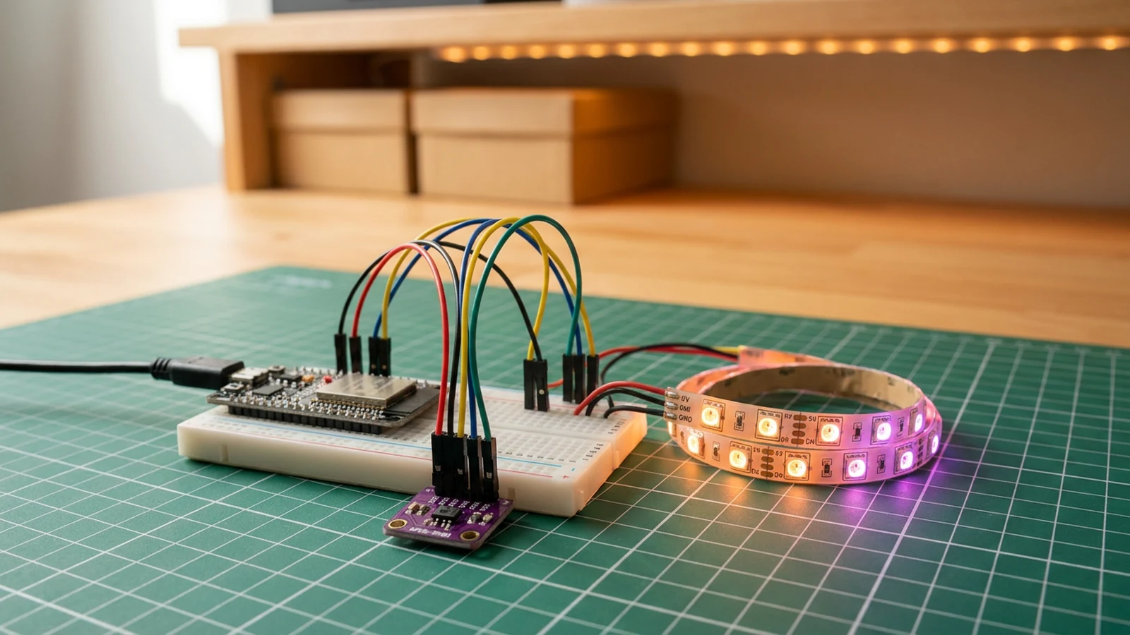
Build a gesture-controlled mood lamp using an ESP32, an APDS-9960 Gesture Sensor, and a WS2812B LED Strip. Swipe left or right to shift the colour, swipe up or down to adjust brightness. The current colour and brightness save automatically to flash five seconds after your last gesture, so the lamp restores its state after a power cycle.
The APDS-9960 combines gesture detection, proximity sensing, and ambient light measurement in a single I2C breakout. The ESP32 reads gesture interrupts in the main loop and passes the result to FastLED. There is no app, no Wi-Fi setup, and no buttons — the lamp responds only to hand movements held 5–10 cm above the sensor.
The firmware has four jobs: initialise the APDS-9960 over I2C and enable gesture detection; translate left/right gestures to hue changes and up/down gestures to brightness changes; drive the WS2812B LED Strip with FastLED using the current hue and brightness; and save colour and brightness to the ESP32's non-volatile Preferences storage after five seconds of inactivity.
Upload and calibrate
Flash the sketch from Schematik and open Serial Monitor at 115200 baud. On boot you should see Mood Lamp ready. The LEDs light at the last saved colour and brightness, or a default colour on first boot.
Swipe left or right horizontally over the sensor to shift the hue. Swipe up or down to adjust brightness. Each swipe shifts hue by 24 steps on a 256-step wheel, and brightness by 15 steps on a 255-step scale. After five seconds of no gesture the current state saves to Preferences. Cycle the power and confirm the lamp restores the same colour.
The default strip length is 16 LEDs. If your strip is longer or shorter, update NUM_LEDS in the firmware and re-flash.
Troubleshooting
- APDS-9960 init fails on boot (
APDS-9960 init failedin Serial). Confirm SDA is GPIO 21 and SCL is GPIO 22, and that the sensor VCC is on 3.3 V. The default I2C address for APDS-9960 is 0x39 — some breakout versions differ, though this is uncommon. - Gestures not detected or misfiring. Hold your hand 5–10 cm above the sensor. Bright direct light from above can swamp the photodiodes; shade the sensor or reduce ambient light. Confirm INT is connected to GPIO 27 with
INPUT_PULLUP. - First LED burns out. Power-on inrush without the 470 µF capacitor can damage the first LED in a strip. Replace the LED and add the capacitor before powering up again.
- State does not save. Preferences writes happen five seconds after the last gesture. If you power off immediately after a gesture, the new colour has not saved yet. Wait for the five-second window before cycling power.
Going further
With gesture control and persistent state in place, a straightforward next step is adding Wi-Fi so you can also set colour from a browser. The Voice-Controlled Robot Face shows the pattern for hosting a small web page on the ESP32 that accepts GET requests to change state. For a multi-lamp setup, each ESP32 could subscribe to an MQTT topic and change colour together, turning the gesture on one lamp into a group scene change across a room.
Wiring diagram
Gather all the parts
Assemble it in 4 steps
1. Wire the low-voltage sensor and controls
Power the APDS-9960 from ESP32 3V3 and connect SDA to GPIO21, SCL to GPIO22, INT to GPIO27, and GND to common ground.
2. Build the regulated 5 V LED rail
Plug the 5 V USB-C supply into the socket breakout. Connect breakout VBUS/5V to WS2812B LED strip 5V and 74AHCT125 VCC. Connect breakout GND, ESP32 GND, WS2812B LED strip GND, and 74AHCT125 GND together. Place the bulk capacitor across 5 V and GND at the LEDs, observing polarity. Tie unused inputs 2A, 3A, and 4A to GND and unused enables 2OE, 3OE, and 4OE to 5 V.
- Unplug the supply while wiring. Verify 5 V polarity with a multimeter before connecting the LEDs or ESP32.
3. Buffer the LED data signal
Connect ESP32 GPIO4 to 74AHCT125 input 1A, tie 1OE to GND, and connect output 1Y through the 220 Ω resistor to WS2812B LED strip DIN. Do not connect GPIO4 directly to DIN. Tie unused inputs 2A, 3A, and 4A to GND and unused enables 2OE, 3OE, and 4OE to 5 V.
4. Upload, test, and calibrate
Upload the sketch, open Serial Monitor at 115200 baud, verify every input and output, then perform the calibration described in the guide before enclosing the project.
Review all connections
1. Connections between "apds9960-1" and "ESP32"
2. Connections between "mood-lamp-bulk-capacitor-1" and "ESP32"
3. Connections between "mood-lamp-led-data-resistor-1" and "ESP32"
4. Connections between "mood-lamp-logic-level-shifter-1" and "ESP32"
5. Connections between "mood-lamp-regulated-5v-supply-1" and "ESP32"
6. Connections between "mood-lamp-usb-c-power-breakout-1" and "ESP32"
7. Connections between "ws2812b-1" and "ESP32"
Deploy the firmware
#include <Wire.h>
#include <Adafruit_APDS9960.h>
#include <FastLED.h>
#include <Preferences.h>

#define APDS_INT_PIN 27
#define LED_PIN 4
#define NUM_LEDS 16
#define SDA_PIN 21
#define SCL_PIN 22

Adafruit_APDS9960 apds;
CRGB leds[NUM_LEDS];
Preferences prefs;

uint8_t hue = 0;
uint8_t brightness = 140;
uint8_t savedHue = 0;
uint8_t savedBrightness = 140;
unsigned long lastGestureMs = 0;

void setup() {
  Serial.begin(115200);
  delay(100);

  prefs.begin("moodlamp", false);
  hue = prefs.getUChar("hue", 0);
  brightness = prefs.getUChar("bright", 140);
  savedHue = hue;
  savedBrightness = brightness;

  Wire.begin(SDA_PIN, SCL_PIN);
  pinMode(APDS_INT_PIN, INPUT_PULLUP);

  FastLED.addLeds<NEOPIXEL, LED_PIN>(leds, NUM_LEDS);
  FastLED.setBrightness(brightness);

  if (!apds.begin()) {
    Serial.println("APDS-9960 init failed");
  }
  apds.enableProximity(true);
  apds.enableGesture(true);
  Serial.println("Mood Lamp ready");
}

void loop() {
  if (apds.gestureValid()) {
    int g = apds.readGesture();
    if (g == APDS9960_LEFT)  hue += 24;
    if (g == APDS9960_RIGHT) hue -= 24;
    if (g == APDS9960_UP   && brightness < 245) brightness += 15;
    if (g == APDS9960_DOWN && brightness > 20)  brightness -= 15;
    FastLED.setBrightness(brightness);
    lastGestureMs = millis();
  }

  if (millis() - lastGestureMs > 5000 && lastGestureMs > 0) {
    if (hue != savedHue || brightness != savedBrightness) {
      prefs.putUChar("hue", hue);
      prefs.putUChar("bright", brightness);
      savedHue = hue;
      savedBrightness = brightness;
    }
    lastGestureMs = 0;
  }

  fill_rainbow(leds, NUM_LEDS, hue, 4);
  FastLED.show();
  delay(20);
}
Remix this project
Make it yours in one click
Open a full copy of this project in your own Schematik workspace — diagram, code, parts, and assembly steps included. Swap the sensor, add features, or redesign the whole thing with AI. The author's original stays untouched.
Related projects
How to Build a Plant Disco Guardian with ESP32
ESP32 · Beginner · 35 minutes · July 22, 2026Schematik
How to Build an Arcade Reaction Tower with ESP32
ESP32 · Beginner · 40 minutes · June 12, 2026Schematik
How to Build a Laser Harp Synth with ESP32
ESP32 · Beginner · 40 minutes · June 12, 2026Schematik