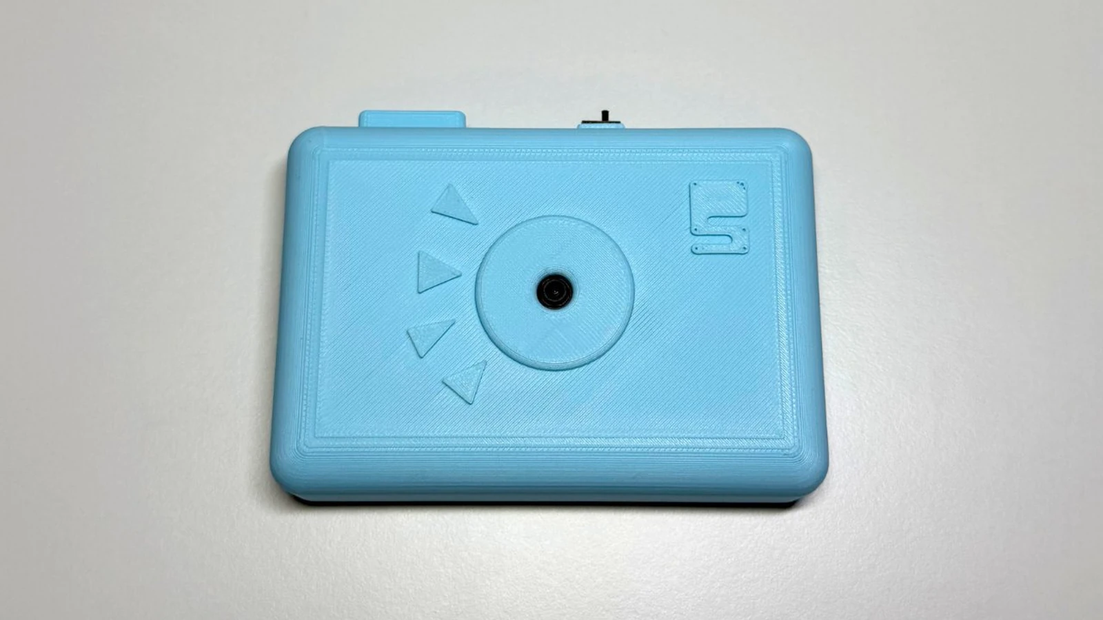
Schematik build
How to Build an ESP32-CAM Setup Portal Security Camera
A tiny camera that sets up its own Wi-Fi portal and can recover without rewriting code
What you'll build
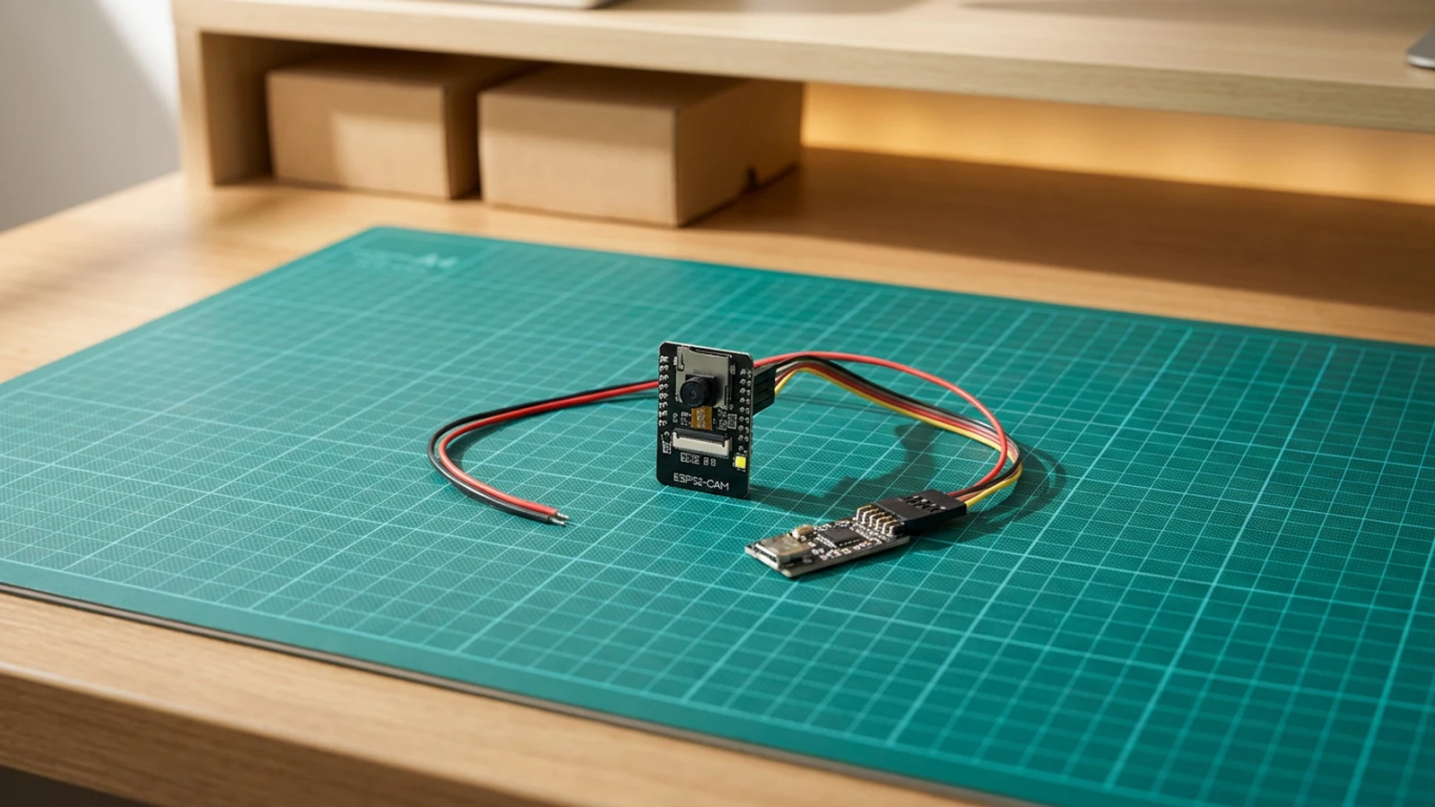
This guide turns an ESP32-CAM into a small security camera that behaves more like a finished gadget than a loose development board. On first boot it creates its own setup Wi-Fi network, serves a browser page for your home Wi-Fi details, then joins that network so you can open the camera locally. If you need to move it to a new network, the sketch has a /reset page that clears the saved credentials and reboots back into setup mode — no USB, no code editing required.
The build uses the AI Thinker ESP32-CAM, its onboard OV2640 camera, and the built-in flash LED on GPIO 4. There is very little external wiring once the board is programmed. The guide pays particular attention to the parts that trip people up: stable 5 V power, how to enter upload mode, reading Serial Monitor, and why FLASH_LED_PIN is driven low on boot.
The result is a workshop or desk camera you can flash from Schematik, configure from your phone, and keep improving later with motion alerts, a printed enclosure, or a better mounting bracket.
What you are building
The firmware has five jobs:
- on first boot (no saved credentials), start a Wi-Fi access point named
ESP32-CAM-Setupand serve a configuration form athttp://192.168.4.1, - save the submitted SSID and password to non-volatile storage using
Preferences, - on subsequent boots, read those credentials and join the home network in station mode,
- serve JPEG captures at
/captureand a simple root page at/, - clear credentials and reboot when
/resetis requested, returning the board to setup mode.
Holding FLASH_LED_PIN low on boot prevents an unwanted flash burst during camera initialisation. The RESET_HOLD_SECONDS constant (currently 8) is defined but not used for a long-press reset in this version; the web /reset route is the recovery path.
Upload and calibrate
There are no Wi-Fi credentials to edit before the first flash — the portal handles that at runtime. The two constants worth knowing are:
#define FLASH_LED_PIN     4
#define RESET_HOLD_SECONDS 8
FLASH_LED_PIN is held LOW immediately in setup() to prevent a flash burst on boot. RESET_HOLD_SECONDS is defined for future use; the current recovery path is the web /reset route, not a long press.
After flashing and resetting:
- On your phone or laptop, join the
ESP32-CAM-SetupWi-Fi network. - Open
http://192.168.4.1and enter your home 2.4 GHz network name and password. - The board saves the credentials and reboots. Serial Monitor shows the local IP address once it connects.
- Open
http://<local-ip>from a device on the same network. The root page links to/capturefor a single frame and/resetto wipe credentials.
If the stream is slow, the frame size is set to FRAMESIZE_VGA. Reducing it to FRAMESIZE_QVGA in configureCamera() will speed up the response on crowded networks.
Troubleshooting
- Board boots into setup portal every time even after saving credentials. The
Preferenceskey"cam-portal"may not have written. Check that the save form posted to/savesuccessfully (Serial Monitor shows a reboot message) and that the board is not browning out mid-save due to an underpowered supply. - "Camera init failed" in Serial Monitor. Wrong board profile selected, or the camera ribbon is not fully seated. Re-select AI Thinker ESP32-CAM and reseat the ribbon.
- Cannot connect to
ESP32-CAM-Setupnetwork. The board may have silently joined a previously saved network. Check Serial Monitor — if it shows a local IP, the credentials were already saved from a previous session. /resetpage returns a response but the board does not reboot. Supply voltage may be dropping during the reboot. Ensure the 5 V rail can handle the inrush on restart.- ESP32-CAM resets during capture. The camera and Wi-Fi together draw significant current. Switch from USB to a dedicated 5 V supply rated at 1 A or more.
- Flash LED turns on during boot unexpectedly. An earlier sketch left GPIO 4 in an unexpected state. The current sketch drives it
LOWat the start ofsetup()— after reflashing this should not recur.
Going further
The setup portal pattern works well for any ESP32 project that needs field-configurable credentials. Once you are comfortable with the Preferences storage and the AP/STA mode switch, you can extend the portal form to capture other settings — MQTT broker address, frame rate, or a device name — without adding any libraries.
For a version of the camera with a physical doorbell button, a passive buzzer chime, and a ring counter in the browser page, see the ESP32 Video Doorbell guide.
Wiring diagram
Gather all the parts
Assemble it in 5 steps
1. Prepare the ESP32-CAM
Fit the OV2640 camera ribbon firmly into the ESP32-CAM socket and mount the board so the antenna is not boxed in metal.
2. Connect the USB serial programmer
Wire programmer 5V to ESP32-CAM 5V, GND to GND, U0R to programmer TX, and U0T to programmer RX. Link IO0 to GND only while flashing.
3. Flash and open Serial Monitor
Upload the sketch, remove the IO0 to GND link, press reset, and watch Serial Monitor at 115200 baud.
4. Join the setup portal
On first boot, connect to the camera setup Wi-Fi network, open http://192.168.4.1, and save your 2.4 GHz Wi-Fi name and password.
5. Power and place the camera
Move to a stable 5V supply. Use the printed local IP address from Serial Monitor or the setup page to open the private camera stream.
Review all connections
1. Connections between "esp32-cam" and "ESP32"
2. Connections between "esp32-cam-setup-portal-security-camera-beefy3-programmer-1" and "ESP32"
3. Connections between "esp32-cam-setup-portal-security-camera-regulated-5v-supply-1" and "ESP32"
4. Connections between "esp32-cam-setup-portal-security-camera-usb-c-power-breakout-1" and "ESP32"
Deploy the firmware
#include <WiFi.h>
#include <WebServer.h>
#include <Preferences.h>
#include "esp_camera.h"

#define FLASH_LED_PIN 4
#define RESET_HOLD_SECONDS 8

// AI Thinker ESP32-CAM pin map
#define PWDN_GPIO_NUM 32
#define RESET_GPIO_NUM -1
#define XCLK_GPIO_NUM 0
#define SIOD_GPIO_NUM 26
#define SIOC_GPIO_NUM 27
#define Y9_GPIO_NUM 35
#define Y8_GPIO_NUM 34
#define Y7_GPIO_NUM 39
#define Y6_GPIO_NUM 36
#define Y5_GPIO_NUM 21
#define Y4_GPIO_NUM 19
#define Y3_GPIO_NUM 18
#define Y2_GPIO_NUM 5
#define VSYNC_GPIO_NUM 25
#define HREF_GPIO_NUM 23
#define PCLK_GPIO_NUM 22

Preferences prefs;
WebServer server(80);
String ssid;
String pass;

void startSetupPortal();
void startCameraServer();

bool configureCamera() {
  camera_config_t config;
  config.ledc_channel = LEDC_CHANNEL_0;
  config.ledc_timer = LEDC_TIMER_0;
  config.pin_d0 = Y2_GPIO_NUM;
  config.pin_d1 = Y3_GPIO_NUM;
  config.pin_d2 = Y4_GPIO_NUM;
  config.pin_d3 = Y5_GPIO_NUM;
  config.pin_d4 = Y6_GPIO_NUM;
  config.pin_d5 = Y7_GPIO_NUM;
  config.pin_d6 = Y8_GPIO_NUM;
  config.pin_d7 = Y9_GPIO_NUM;
  config.pin_xclk = XCLK_GPIO_NUM;
  config.pin_pclk = PCLK_GPIO_NUM;
  config.pin_vsync = VSYNC_GPIO_NUM;
  config.pin_href = HREF_GPIO_NUM;
  config.pin_sscb_sda = SIOD_GPIO_NUM;
  config.pin_sscb_scl = SIOC_GPIO_NUM;
  config.pin_pwdn = PWDN_GPIO_NUM;
  config.pin_reset = RESET_GPIO_NUM;
  config.xclk_freq_hz = 20000000;
  config.pixel_format = PIXFORMAT_JPEG;
  config.frame_size = FRAMESIZE_VGA;
  config.jpeg_quality = 12;
  config.fb_count = psramFound() ? 2 : 1;
  config.fb_location = CAMERA_FB_IN_PSRAM;
  return esp_camera_init(&config) == ESP_OK;
}

void handleRoot() {
  server.send(200, "text/html", "<h1>ESP32-CAM</h1><p><a href='/capture'>Capture frame</a></p><p><a href='/reset'>Reset Wi-Fi setup</a></p>");
}

void handleCapture() {
  camera_fb_t *fb = esp_camera_fb_get();
  if (!fb) {
    server.send(503, "text/plain", "Camera capture failed");
    return;
  }
  server.sendHeader("Content-Disposition", "inline; filename=capture.jpg");
  server.send_P(200, "image/jpeg", (const char *)fb->buf, fb->len);
  esp_camera_fb_return(fb);
}

void setup() {
  pinMode(FLASH_LED_PIN, OUTPUT);
  digitalWrite(FLASH_LED_PIN, LOW);
  Serial.begin(115200);
  delay(200);

  prefs.begin("cam-portal", false);
  ssid = prefs.getString("ssid", "");
  pass = prefs.getString("pass", "");

  if (ssid.length() == 0) {
    startSetupPortal();
    return;
  }

  WiFi.mode(WIFI_STA);
  WiFi.begin(ssid.c_str(), pass.c_str());
  Serial.print("Joining Wi-Fi");
  for (int i = 0; i < 40 && WiFi.status() != WL_CONNECTED; i++) {
    delay(250);
    Serial.print('.');
  }
  Serial.println();

  if (WiFi.status() != WL_CONNECTED || !configureCamera()) {
    startSetupPortal();
    return;
  }
  startCameraServer();
}

void startSetupPortal() {
  WiFi.mode(WIFI_AP);
  WiFi.softAP("ESP32-CAM-Setup");
  server.on("/", HTTP_GET, []() {
    server.send(200, "text/html", "<form method='post' action='/save'><label>Wi-Fi name <input name='s'></label><br><label>Password <input name='p' type='password'></label><br><button>Save</button></form>");
  });
  server.on("/save", HTTP_POST, []() {
    prefs.putString("ssid", server.arg("s"));
    prefs.putString("pass", server.arg("p"));
    server.send(200, "text/plain", "Saved. Rebooting into camera mode.");
    delay(500);
    ESP.restart();
  });
  server.begin();
  Serial.println("Setup portal: http://192.168.4.1");
}

void startCameraServer() {
  server.on("/", handleRoot);
  server.on("/capture", handleCapture);
  server.on("/reset", []() {
    prefs.clear();
    server.send(200, "text/plain", "Wi-Fi settings cleared. Rebooting.");
    delay(500);
    ESP.restart();
  });
  server.begin();
  Serial.print("Camera page: http://");
  Serial.println(WiFi.localIP());
}

void loop() {
  server.handleClient();
}
Remix this project
Make it yours in one click
Open a full copy of this project in your own Schematik workspace — diagram, code, parts, and assembly steps included. Swap the sensor, add features, or redesign the whole thing with AI. The author's original stays untouched.
Related projects
How to Build an ESP32 Security Camera
ESP32 · Beginner · 25 minutes · July 22, 2026Schematik
How to Build an RFID Treasure Chest with ESP32
ESP32 · Intermediate · 50 minutes · June 12, 2026Schematik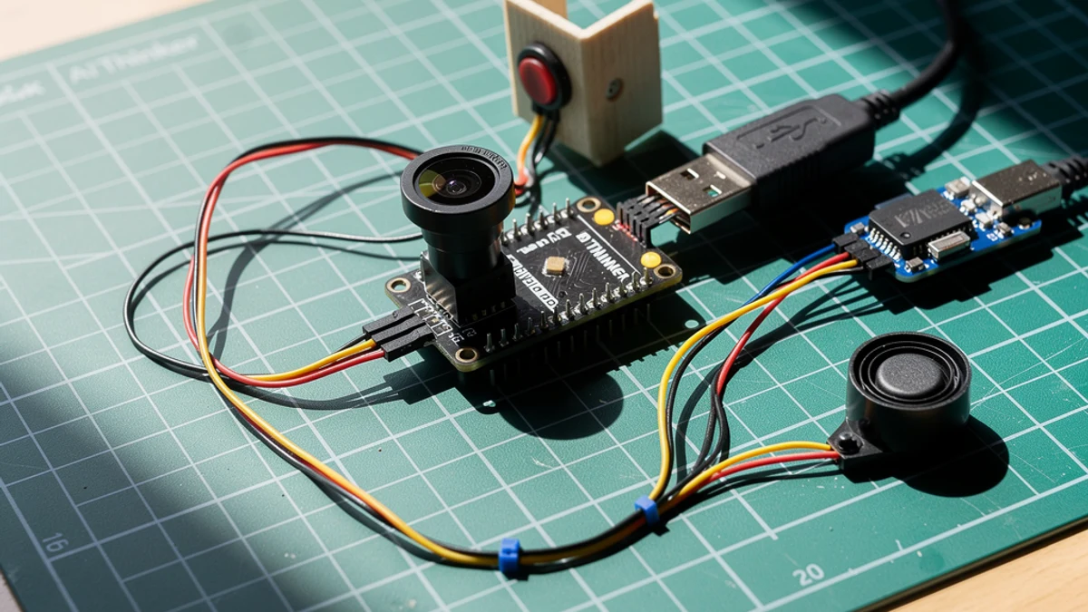
How to Build an ESP32 Video Doorbell
ESP32 · Intermediate · 45 minutes · July 22, 2026Schematik