Community project
Diseño De Circuito ESP32
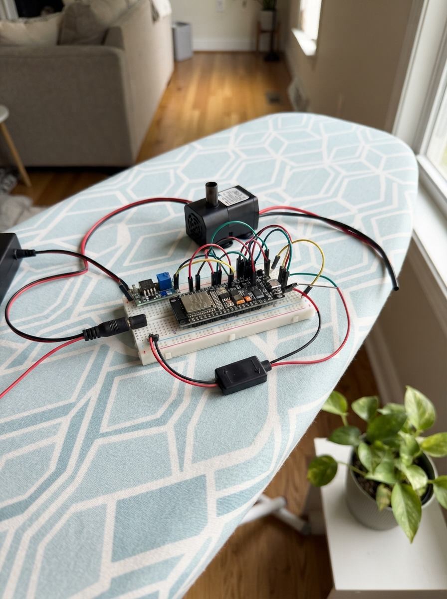
This ESP32-based water dome filter control system automates pump operation using float switches to maintain optimal water levels. The circuit combines a 12V power supply, buck converter for logic-level voltage, MOSFET driver for pump control, and protective diode to prevent back-EMF damage.
Builders will receive a complete wiring diagram showing connections between the barrel-jack adapter, MP1584 converter, float switches, and pump control circuit, along with a full parts list, Arduino firmware for automated water level management, and step-by-step assembly instructions including dry testing before final sealing.
Wiring diagram

Gather all the parts
Assemble it in 6 steps
1. Prepara la parte hidráulica de la cúpula
Imprime la cúpula, la cesta y la cámara inferior en PETG u otro material realmente impermeable. Coloca la junta tórica continua en su ranura y aprieta los ocho tornillos M5 de forma alternada, un poco cada vez, para que la junta selle por igual.
- La cesta debe poder extraerse sin tocar el compartimento seco.
- No sumerjas la parte electrónica ni confíes solo en plástico poroso: una fuga puede dañar el ESP32 y causar un cortocircuito.
2. Coloca bomba y los dos flotadores
Pon la bomba dentro de la zona húmeda, con su entrada libre de residuos. Monta float_low para que su contacto se cierre cuando el nivel de agua baje demasiado, y float_high para que su contacto se cierre cuando el nivel suba hasta el punto de desborde. Lleva sus cables por prensaestopas hacia el compartimento seco.
- Antes de sellar, mueve cada flotador con la mano y comprueba que puede subir y bajar sin rozar la cesta.
- Mantén los empalmes de la bomba y de los flotadores fuera del agua; el agua puede entrar por un cable mal sellado.
3. Cablea la alimentación de 12 V y el reductor
Con la fuente desenchufada, conecta +12V de supply_12v a VIN de buck_5v y también a VIN+ de pump_switch. Conecta GND de supply_12v a GND de buck_5v y también a VIN- de pump_switch. Ajusta buck_5v a exactamente 5,0 V antes de unir su salida al ESP32. Conecta VOUT de buck_5v al pin VIN/5V del ESP32 y conecta su GND a GND del ESP32.
- Mide la salida del reductor con un multímetro antes de enchufarla al ESP32.
- No conectes los 12 V directamente al ESP32: puede dañarlo de forma permanente.
4. Conecta la bomba y el diodo protector
Conecta LOAD+ de pump_switch a PUMP+ de pump_12v y LOAD- a PUMP- de pump_12v. Conecta el diodo flyback_diode en paralelo con la bomba: la pata sin banda (Anode) va a PUMP- y la pata con banda (Cathode) va a PUMP+.
- La banda pintada del diodo debe mirar al positivo de la bomba.
- Si inviertes el diodo, la fuente puede quedar en cortocircuito cuando enciendas la bomba.
5. Conecta señales de control
Conecta PWM de pump_switch a GPIO25 del ESP32 y CTRL-GND de pump_switch a GND del ESP32. Conecta el cable GND de float_low a GND y su cable SIGNAL a GPIO32. Conecta el cable GND de float_high a GND y su cable SIGNAL a GPIO33.
- GPIO32 y GPIO33 se usan solo como entradas y el programa activa una resistencia interna para leer los flotadores con dos cables.
- Todas las tierras deben estar unidas; sin la tierra compartida, el ESP32 no puede controlar el módulo de bomba de forma fiable.
6. Haz una prueba seca antes de sellar
Con la bomba fuera del agua o con su manguera dirigida a un recipiente, enchufa la fuente. Mantén ambos flotadores en su estado seguro: tras dos segundos la bomba debe encender. Activa cualquiera de los flotadores: la bomba debe detenerse de inmediato. Si funciona, cierra el compartimento seco y prueba el conjunto bajo supervisión.
- Prueba primero con agua limpia y revisa que no haya gotas dentro del compartimento seco.
- Una bomba sumergible no debe funcionar en seco durante mucho tiempo; puede calentarse y averiarse.
Review all connections
1. Connections between "supply_12v" and "ESP32"
2. Connections between "buck_5v" and "ESP32"
3. Connections between "pump_switch" and "ESP32"
4. Connections between "flyback_diode" and "ESP32"
5. Connections between "float_low" and "ESP32"
6. Connections between "float_high" and "ESP32"
Deploy the firmware
#include <Arduino.h>

// Control de bomba para la cúpula de filtro de agua.
// Los flotadores se cablean a GND y se leen con resistencias internas INPUT_PULLUP.

constexpr int PUMP_PWM_PIN = 25;
constexpr int LOW_LEVEL_PIN = 32;
constexpr int HIGH_LEVEL_PIN = 33;

constexpr unsigned long SAMPLE_INTERVAL_MS = 100;
constexpr unsigned long START_DELAY_MS = 2000;

bool pumpRunning = false;
bool lowLevelActive = false;
bool highLevelActive = false;
unsigned long safeSinceMs = 0;
unsigned long lastSampleMs = 0;

void setPump(bool enabled) {
  digitalWrite(PUMP_PWM_PIN, enabled ? HIGH : LOW);
  pumpRunning = enabled;
}

void setup() {
  pinMode(PUMP_PWM_PIN, OUTPUT);
  setPump(false); // La bomba nunca arranca durante el encendido.

  pinMode(LOW_LEVEL_PIN, INPUT_PULLUP);
  pinMode(HIGH_LEVEL_PIN, INPUT_PULLUP);

  Serial.begin(115200);
  Serial.println("Control de cupula filtro iniciado");
}

void loop() {
  const unsigned long now = millis();
  if (now - lastSampleMs < SAMPLE_INTERVAL_MS) {
    return;
  }
  lastSampleMs = now;

  // Un contacto cerrado une SIGNAL con GND y por eso se lee como LOW.
  lowLevelActive = digitalRead(LOW_LEVEL_PIN) == LOW;
  highLevelActive = digitalRead(HIGH_LEVEL_PIN) == LOW;

  // El flotador bajo se instala para cerrar cuando falta agua.
  // El flotador alto se instala para cerrar cuando el depósito se llena demasiado.
  const bool fault = lowLevelActive || highLevelActive;

  if (fault) {
    safeSinceMs = 0;
    if (pumpRunning) {
      setPump(false);
      Serial.println(lowLevelActive ? "Bomba detenida: nivel bajo" : "Bomba detenida: nivel alto");
    }
    return;
  }

  if (safeSinceMs == 0) {
    safeSinceMs = now;
  }

  if (!pumpRunning && now - safeSinceMs >= START_DELAY_MS) {
    setPump(true);
    Serial.println("Bomba encendida: niveles seguros");
  }
}
Remix this project
Make it yours in one click
Open a full copy of this project in your own Schematik workspace — diagram, code, parts, and assembly steps included. Swap the sensor, add features, or redesign the whole thing with AI. The author's original stays untouched.