Community project
Battery Health Screening Device
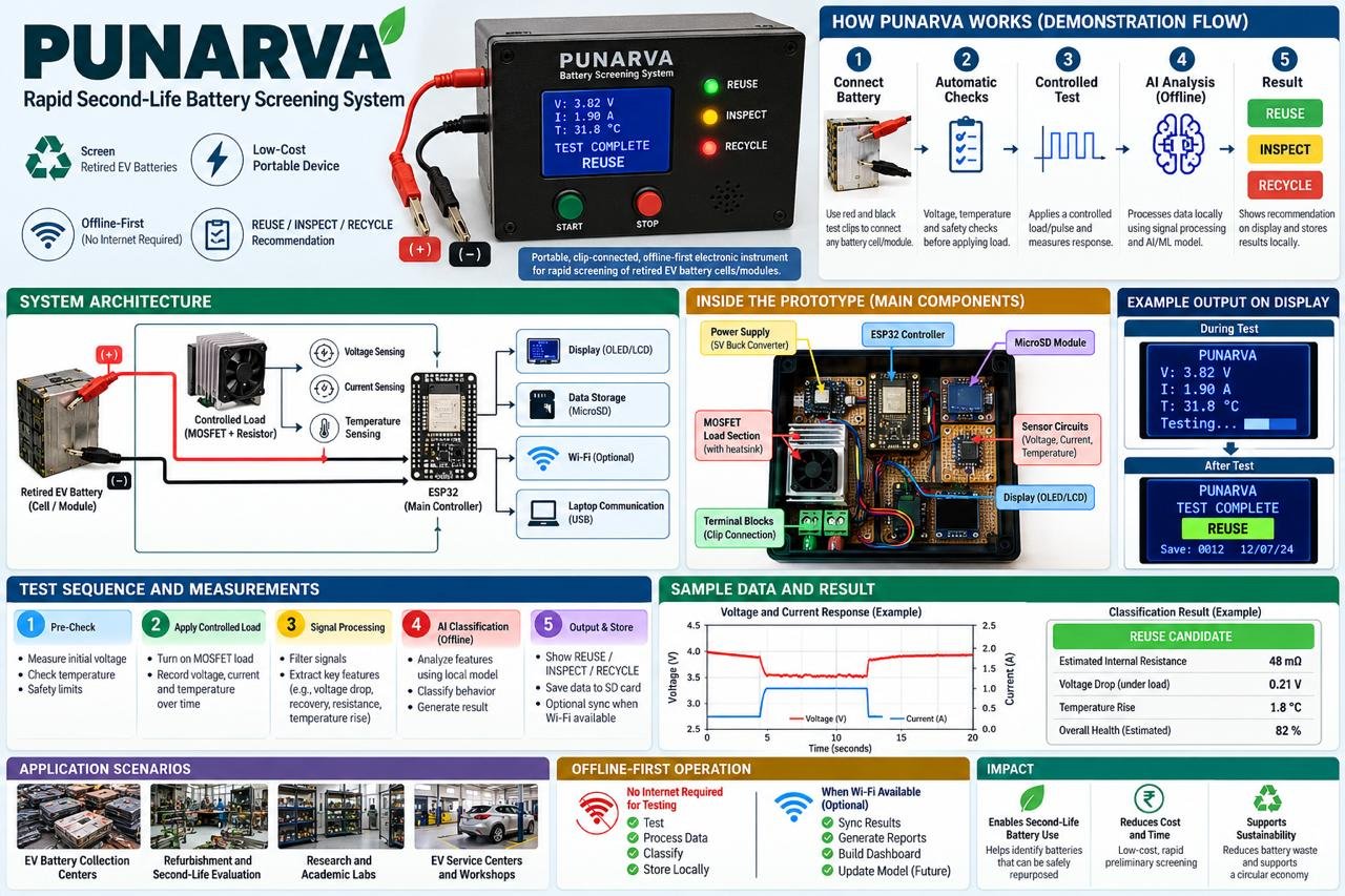
This battery health screening device measures the capacity and condition of single-cell 18650 lithium batteries by applying a controlled load and monitoring voltage, current, and temperature over a 30-second test cycle. The ESP32 controller manages a MOSFET-switched load path, records real-time data to an SD card, and displays results on an OLED screen with LED indicators and audio feedback.
Builders will receive a complete wiring diagram, parts list, and firmware that implements voltage divider measurement via the ADS1115 ADC, current sensing through the INA219 module, and NTC thermistor temperature compensation. The guide covers safe assembly of the battery fixture and load circuit, configuration of the test parameters, and interpretation of the pass/inspect/recycle outcomes.
Wiring diagram

Gather all the parts
Assemble it in 7 steps
1. Keep the controller on USB power
Place the ESP32 across the breadboard center gap, then power it only from its USB socket while you build. Run one short black jumper from an ESP32 GND pin to the breadboard ground rail and one red jumper from 3V3 to a separate 3.3 V rail; do not connect the 18650 positive lead to either ESP32 power pin.
- Use the USB cable both for power and later firmware deployment.
- Never power the ESP32 from the cell being tested; a failing cell can pull the controller voltage down or damage modules.
2. Build the protected battery and load path
With no cell installed, connect the red battery-fixture lead to the emergency-stop COM terminal, the emergency-stop NC terminal to the fuse IN terminal, fuse OUT to INA219 VIN+, INA219 VIN- to one end of the 4.7 Ω 10 W resistor, and the other end of that resistor to the MOSFET DRAIN. Connect MOSFET SOURCE to the ground rail. This is the high-current path: cell positive → safety switch → fuse → current sensor → hot load resistor → MOSFET → cell negative.
- Use the thick test leads for every wire from the cell through the resistor and MOSFET.
- For a TO-220 IRLZ44N with the flat labelled face toward you and legs down, the usual leg order is Gate, Drain, Source; confirm against the marking or datasheet of your exact part.
- Keep the 10 W resistor and MOSFET heatsink off the breadboard and away from plastic; the resistor becomes hot during a test.
- Press the emergency stop before changing any test-path wiring or inserting/removing a cell.
3. Wire the MOSFET control safely
Connect ESP32 GPIO25 to one end of the 100 Ω gate resistor, and connect its other end to the MOSFET GATE. Connect the 10 kΩ gate pulldown between that same GATE point and the ground rail. The resistor makes the MOSFET stay off while the ESP32 starts up.
- Keep the gate wires short and separate from the thick resistor wires.
- Do not omit the 10 kΩ resistor: without it, the load can turn on unexpectedly during reset.
4. Add voltage and temperature measurement
Connect INA219 VIN- to the 20 kΩ resistor, connect the other end of that resistor to ADS1115 AIN0, then connect the 10 kΩ voltage-divider resistor from AIN0 to ground. This reduces the cell voltage to a safe value for the ADS1115. Tape the two-lead 10 kΩ NTC thermistor firmly against the insulated side of the cell. Connect one NTC lead to ground and the other NTC lead to ADS1115 AIN1; connect the remaining fixed 10 kΩ resistor from 3V3 to AIN1.
- Use thermal tape to hold the NTC against the cell body, not across either battery terminal.
- The 20 kΩ and 10 kΩ voltage-divider resistors must be in the stated order: 20 kΩ from cell sense point to AIN0, 10 kΩ from AIN0 to ground.
- A divider wired backwards can expose the ADC input to too much voltage and damage it.
5. Connect the shared screen and sensor wires
Connect 3V3 and ground to the ADS1115, INA219, and OLED. Join every SDA pin from these three modules to ESP32 GPIO21, and join every SCL pin to ESP32 GPIO22. Tie ADS1115 ADDR to ground so it uses address 0x48.
- All three boards share the same two data wires; that is normal.
- Use 3.3 V for every I²C module so their data wires never rise above the ESP32’s safe 3.3 V level.
- Make sure VCC and GND are not swapped — swapped power can damage the screen or sensor modules.
6. Connect the SD card, buttons, buzzer, and result lights
Power the MicroSD module from 3V3 and ground. Connect SD MISO to GPIO19, MOSI to GPIO23, SCK to GPIO18, and CS to GPIO4. Connect each push button between its signal pin and ground: START to GPIO32 and STOP to GPIO33. Connect buzzer SIGNAL to GPIO27 and its other lead to ground. For each LED, wire GPIO13 through its 220 Ω resistor to the green LED long leg, GPIO14 through its 220 Ω resistor to the yellow LED long leg, and GPIO26 through its 220 Ω resistor to the red LED long leg; connect all three short legs to ground.
- The LED long leg is the positive leg; each LED needs its own 220 Ω resistor.
- Use a 3.3 V-compatible MicroSD module. Some inexpensive 5 V-labelled modules do not work reliably from 3.3 V.
- Never connect an LED directly to a GPIO; its 220 Ω resistor prevents excessive current.
- GPIO4 is the MicroSD card-select wire; do not let it touch ground during reset.
7. Inspect before inserting the battery
With USB connected but no battery installed, check that the OLED says READY and all three result LEDs are off. Keep the emergency stop released so its normally-closed contact is connected. Insert only one undamaged protected 18650 cell in the correct holder polarity, then press START for the 30-second low-current test.
- Use the STOP button for a normal abort; press the red emergency stop immediately if a wire, resistor, MOSFET, or cell becomes unusually hot.
- The result is a screening result, not a certification of battery safety; visibly damaged, swollen, leaking, or very hot cells must not be tested.
- Never test loose cells, cells with torn insulation, cells above 4.25 V, or cells below 3.00 V.
- Do not leave a battery test unattended.
Review all connections
1. Connections between "battery_fixture_1" and "ESP32"
2. Connections between "estop_1" and "ESP32"
3. Connections between "test_fuse_1" and "ESP32"
4. Connections between "ina219_1" and "ESP32"
5. Connections between "load_resistor_1" and "ESP32"
6. Connections between "mosfet_1" and "ESP32"
7. Connections between "voltage_divider_top_1" and "ESP32"
8. Connections between "voltage_divider_bottom_1" and "ESP32"
9. Connections between "ads1115_1" and "ESP32"
10. Connections between "ntc_fixed_resistor_1" and "ESP32"
11. Connections between "oled_1" and "ESP32"
12. Connections between "microsd_1" and "ESP32"
13. Connections between "gate_resistor_1" and "ESP32"
14. Connections between "gate_pulldown_1" and "ESP32"
15. Connections between "start_button_1" and "ESP32"
16. Connections between "stop_button_1" and "ESP32"
17. Connections between "buzzer_1" and "ESP32"
18. Connections between "reuse_led_resistor_1" and "ESP32"
19. Connections between "reuse_led_1" and "ESP32"
20. Connections between "inspect_led_resistor_1" and "ESP32"
21. Connections between "inspect_led_1" and "ESP32"
22. Connections between "recycle_led_resistor_1" and "ESP32"
23. Connections between "recycle_led_1" and "ESP32"
24. Connections between "ntc_1" and "ESP32"
Deploy the firmware
#include <Wire.h>
#include <SPI.h>
#include <SD.h>
#include <Adafruit_ADS1X15.h>
#include <Adafruit_INA219.h>
#include <Adafruit_GFX.h>
#include <Adafruit_SSD1306.h>

constexpr int SD_CS_PIN = 4;
constexpr int LOAD_GATE_PIN = 25;
constexpr int START_BUTTON_PIN = 32;
constexpr int STOP_BUTTON_PIN = 33;
constexpr int BUZZER_PIN = 27;
constexpr int REUSE_LED_PIN = 13;
constexpr int INSPECT_LED_PIN = 14;
constexpr int RECYCLE_LED_PIN = 26;

constexpr float DIVIDER_RATIO = 3.0f;       // 20 kOhm top / 10 kOhm bottom divider
constexpr float MIN_START_VOLTAGE = 3.00f;  // Do not test a deeply discharged cell
constexpr float CUTOFF_VOLTAGE = 2.80f;
constexpr float MAX_CELL_TEMP_C = 55.0f;
constexpr unsigned long TEST_DURATION_MS = 30000UL;
constexpr unsigned long SAMPLE_PERIOD_MS = 500UL;
constexpr float NTC_BETA = 3950.0f;
constexpr float NTC_R0 = 10000.0f;
constexpr float NTC_T0_K = 298.15f;

Adafruit_ADS1115 ads;
Adafruit_INA219 ina219;
Adafruit_SSD1306 display(128, 64, &Wire, -1);
bool sdReady = false;
bool testRunning = false;
unsigned long testStartedMs = 0;
unsigned long lastSampleMs = 0;
float openCircuitVoltage = 0.0f;
float minimumVoltage = 99.0f;
float peakCurrentA = 0.0f;
float startTempC = 0.0f;
float lastVoltage = 0.0f;
float lastCurrentA = 0.0f;
float lastTempC = 0.0f;

float readCellVoltage() {
  int16_t raw = ads.readADC_SingleEnded(0);
  float adcVolts = ads.computeVolts(raw);
  return adcVolts * DIVIDER_RATIO;
}

float readTemperatureC() {
  int16_t raw = ads.readADC_SingleEnded(1);
  float nodeVolts = ads.computeVolts(raw);
  if (nodeVolts <= 0.01f || nodeVolts >= 3.29f) return NAN;
  // 10 kOhm fixed resistor is from 3.3 V to the node; NTC is from node to GND.
  float ntcOhms = NTC_R0 * nodeVolts / (3.3f - nodeVolts);
  float invT = (1.0f / NTC_T0_K) + log(ntcOhms / NTC_R0) / NTC_BETA;
  return (1.0f / invT) - 273.15f;
}

float readCurrentA() {
  return ina219.getCurrent_mA() / 1000.0f;
}

void setResultLeds(bool reuse, bool inspect, bool recycle) {
  digitalWrite(REUSE_LED_PIN, reuse ? HIGH : LOW);
  digitalWrite(INSPECT_LED_PIN, inspect ? HIGH : LOW);
  digitalWrite(RECYCLE_LED_PIN, recycle ? HIGH : LOW);
}

void drawStatus(const char *title, const char *line4 = "") {
  display.clearDisplay();
  display.setTextColor(SSD1306_WHITE);
  display.setTextSize(1);
  display.setCursor(0, 0);
  display.println("PUNARVA 18650 TEST");
  display.println(title);
  display.print("V: "); display.print(lastVoltage, 2); display.println(" V");
  display.print("I: "); display.print(lastCurrentA, 2); display.println(" A");
  display.print("T: "); display.print(lastTempC, 1); display.println(" C");
  display.println(line4);
  display.display();
}

void appendLog(const char *result, float resistanceOhms) {
  if (!sdReady) return;
  File log = SD.open("/punarva.csv", FILE_APPEND);
  if (!log) return;
  log.print(millis()); log.print(',');
  log.print(openCircuitVoltage, 3); log.print(',');
  log.print(minimumVoltage, 3); log.print(',');
  log.print(peakCurrentA, 3); log.print(',');
  log.print(lastTempC, 2); log.print(',');
  log.print(resistanceOhms * 1000.0f, 1); log.print(',');
  log.println(result);
  log.close();
}

void finishTest(const char *forcedResult = nullptr) {
  digitalWrite(LOAD_GATE_PIN, LOW);
  testRunning = false;
  float voltageDrop = openCircuitVoltage - minimumVoltage;
  float resistanceOhms = (peakCurrentA > 0.05f) ? voltageDrop / peakCurrentA : 99.0f;
  float temperatureRise = lastTempC - startTempC;
  const char *result = forcedResult;
  if (result == nullptr) {
    if (minimumVoltage < CUTOFF_VOLTAGE || lastTempC >= MAX_CELL_TEMP_C || resistanceOhms > 0.25f) result = "RECYCLE";
    else if (resistanceOhms > 0.12f || temperatureRise > 8.0f || minimumVoltage < 3.20f) result = "INSPECT";
    else result = "REUSE";
  }
  setResultLeds(strcmp(result, "REUSE") == 0, strcmp(result, "INSPECT") == 0, strcmp(result, "RECYCLE") == 0);
  tone(BUZZER_PIN, 2200, 180);
  lastVoltage = minimumVoltage;
  drawStatus(result, "Remove cell before next test");
  appendLog(result, resistanceOhms);
}

void startTest() {
  lastVoltage = readCellVoltage();
  lastCurrentA = readCurrentA();
  lastTempC = readTemperatureC();
  setResultLeds(false, false, false);
  if (isnan(lastTempC) || lastVoltage < MIN_START_VOLTAGE || lastVoltage > 4.25f) {
    drawStatus("CHECK CELL", "Use 3.00-4.25 V cell");
    tone(BUZZER_PIN, 500, 350);
    return;
  }
  openCircuitVoltage = lastVoltage;
  minimumVoltage = lastVoltage;
  peakCurrentA = 0.0f;
  startTempC = lastTempC;
  testStartedMs = millis();
  lastSampleMs = 0;
  testRunning = true;
  digitalWrite(LOAD_GATE_PIN, HIGH);
}

void setup() {
  pinMode(LOAD_GATE_PIN, OUTPUT);
  pinMode(BUZZER_PIN, OUTPUT);
  pinMode(REUSE_LED_PIN, OUTPUT);
  pinMode(INSPECT_LED_PIN, OUTPUT);
  pinMode(RECYCLE_LED_PIN, OUTPUT);
  pinMode(START_BUTTON_PIN, INPUT_PULLUP);
  pinMode(STOP_BUTTON_PIN, INPUT_PULLUP);
  digitalWrite(LOAD_GATE_PIN, LOW);
  setResultLeds(false, false, false);

  Wire.begin(21, 22);
  display.begin(SSD1306_SWITCHCAPVCC, 0x3C);
  ads.begin(0x48);
  ads.setGain(GAIN_ONE);
  ina219.begin();
  SPI.begin(18, 19, 23, SD_CS_PIN);
  sdReady = SD.begin(SD_CS_PIN, SPI);
  lastVoltage = readCellVoltage();
  lastCurrentA = readCurrentA();
  lastTempC = readTemperatureC();
  drawStatus("READY", "Press START to test");
}

void loop() {
  if (!testRunning) {
    if (digitalRead(START_BUTTON_PIN) == LOW) {
      delay(25);
      if (digitalRead(START_BUTTON_PIN) == LOW) {
        startTest();
        while (digitalRead(START_BUTTON_PIN) == LOW) delay(5);
      }
    }
    return;
  }

  if (digitalRead(STOP_BUTTON_PIN) == LOW) {
    finishTest("INSPECT");
    while (digitalRead(STOP_BUTTON_PIN) == LOW) delay(5);
    return;
  }

  unsigned long now = millis();
  if (now - lastSampleMs >= SAMPLE_PERIOD_MS) {
    lastSampleMs = now;
    lastVoltage = readCellVoltage();
    lastCurrentA = readCurrentA();
    lastTempC = readTemperatureC();
    if (lastVoltage < minimumVoltage) minimumVoltage = lastVoltage;
    if (lastCurrentA > peakCurrentA) peakCurrentA = lastCurrentA;
    drawStatus("TESTING", "STOP aborts test");

    if (isnan(lastTempC) || lastTempC >= MAX_CELL_TEMP_C) {
      finishTest("RECYCLE");
      return;
    }
    if (lastVoltage <= CUTOFF_VOLTAGE) {
      finishTest();
      return;
    }
  }

  if (now - testStartedMs >= TEST_DURATION_MS) finishTest();
}
Remix this project
Make it yours in one click
Open a full copy of this project in your own Schematik workspace — diagram, code, parts, and assembly steps included. Swap the sensor, add features, or redesign the whole thing with AI. The author's original stays untouched.