Community project
Fire Alert Field Node
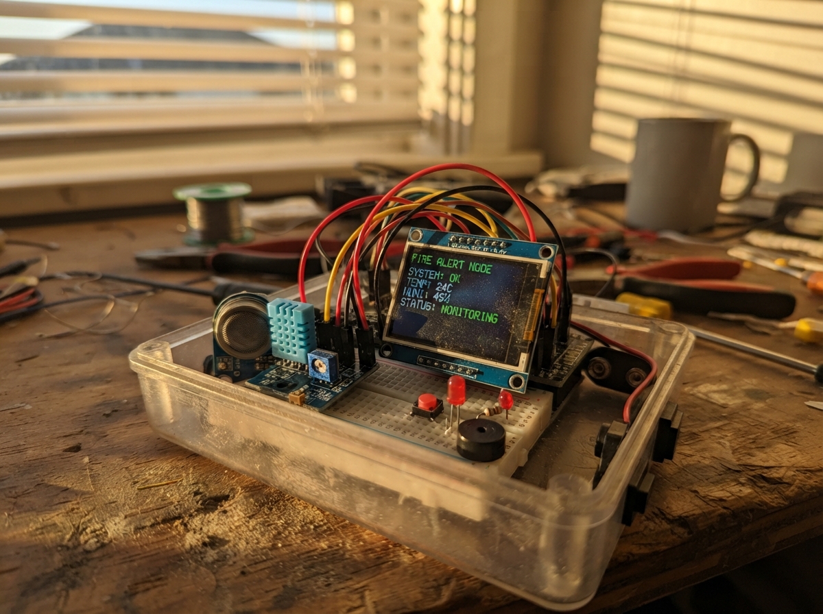
The Fire Alert Field Node is a multi-sensor fire detection system built on an ESP32 that monitors temperature, flame, and smoke in real time. It combines a DHT11 temperature sensor, KY-026 flame detector, and MQ smoke sensor to trigger visual and audible alerts when dangerous conditions are detected, displaying status on a 1.54-inch ST7789 TFT screen.
This guide provides a complete parts list, wiring diagram for two breadboards, and ready-to-compile firmware with configurable alarm thresholds. Builders will learn how to integrate multiple analog and digital sensors, drive an SPI display, and implement debounced button control and latching alarm logic on the ESP32 platform.
Wiring diagram

Gather all the parts
Assemble it in 6 steps
1. Place the ESP32 and prepare both breadboards
Put the ESP32-S3-DevKitC-1 across the centre gap of Breadboard 1. Use one red jumper to join Breadboard 1's 3V3 rail to Breadboard 2's 3V3 rail, and one black jumper to join their GND rails. Run a jumper from the ESP32 3V3 pin to Breadboard 1's 3V3 rail, a jumper from an ESP32 GND pin to Breadboard 1's GND rail, and a jumper from the ESP32 5V pin to Breadboard 2's separate 5V rail.
- Keep the 5V rail physically separate from the 3V3 rail. Label the two Breadboard 2 power rails before fitting modules.
- Never connect the 5V rail to an ESP32 GPIO or to the 3V3 rail — 5V on a GPIO can permanently damage the ESP32.
2. Add the manual alarm, light, and buzzer on Breadboard 1
Place the red tactile button across the breadboard centre gap. Connect one button side to GPIO6 and the opposite side to GND. Connect GPIO15 to one end of led_resistor_1 (220 Ω), the other end to the long leg of led_1, and connect the LED's short flat-side leg to GND. Connect GPIO8 to one end of buzzer_resistor_1 (220 Ω), its other end to the plus-marked terminal of buzzer_1, and connect the buzzer's other terminal to GND.
- The plus mark on the buzzer identifies the terminal that must face the resistor from GPIO8.
- The LED long leg is its positive leg; use the flat edge on its body to find the negative leg.
- Make sure the LED and buzzer polarity are not reversed — swapped connections can prevent the warning outputs from working.
3. Wire the display on Breadboard 2
Connect tft_1 GND to GND, VCC to 3V3, SCL to GPIO12, SDA to GPIO11, CS to GPIO10, DC to GPIO9, RST to GPIO13, and BL to GPIO14. Each signal jumper should be labelled at both ends with its GPIO number.
- SCL on this SPI display is the clock wire, while SDA is the display data wire; they do not go to the ESP32's I2C pins.
- A label on every wire makes later fault-finding much easier.
- Do not connect the display VCC to the 5V rail unless its own board is explicitly marked as 5V-safe — this project uses 3V3.
4. Wire the temperature and flame sensors on Breadboard 2
Connect dht11_1 VCC to 3V3, GND to GND, and DATA to GPIO4. Fit dht_pullup_1 (10 kΩ) between the DHT DATA/GPIO4 row and the 3V3 rail. Connect flame_1 VCC to 3V3, GND to GND, D0 to GPIO5, and A0 to GPIO1. Label DATA as GPIO4, D0 as GPIO5, and A0 as GPIO1.
- The DHT resistor shares the same breadboard row as the DHT DATA-to-GPIO4 jumper.
- Set the flame module's small adjustment screw only after the board is running, because it sets when its D0 output changes.
- Make sure VCC and GND are not swapped on either sensor — swapped power can damage a module.
5. Wire the 5V smoke sensor and safe signal dividers
Connect mq_1 VCC to the separate 5V rail and GND to GND. For AO, connect MQ AO to mq_divider_top_1 (10 kΩ), connect its other end to the GPIO2 row, then connect mq_divider_bottom_1 (10 kΩ) from that same GPIO2 row to GND. For DO, connect MQ DO to mq_do_divider_top_1 (10 kΩ), connect its other end to the GPIO7 row, then connect mq_do_divider_bottom_1 (10 kΩ) from that same GPIO7 row to mq_do_divider_bottom_extra_1 (10 kΩ), then connect the free end of mq_do_divider_bottom_extra_1 to GND. The two 10 kΩ resistors in this lower leg act exactly like one 20 kΩ resistor.
- The two resistors on each output meet at the GPIO row; that meeting row is the safe lower-voltage signal sent to the ESP32.
- Let the MQ sensor warm up in clean air before judging its readings.
- Never connect either raw MQ AO or raw MQ DO pin directly to GPIO2 or GPIO7 — the MQ module is powered from 5V and may output a damaging 5V signal.
6. Check the labelled wiring before power
Confirm the title of this two-breadboard build is “Fire Alert Field Node”. Check every named GPIO label: GPIO1 flame A0, GPIO2 divided MQ AO, GPIO4 DHT DATA, GPIO5 flame D0, GPIO6 button, GPIO7 divided MQ DO, GPIO8 buzzer, GPIO9 TFT DC, GPIO10 TFT CS, GPIO11 TFT SDA, GPIO12 TFT SCL, GPIO13 TFT RST, GPIO14 TFT BL, and GPIO15 LED. The button makes one immediate alarm; sensor thresholds also make one alarm. Once triggered, the LED and buzzer remain on until a future PC or phone gateway sends a clear command; this node has no mute button or hold-time clear.
- With power disconnected, trace each labelled wire slowly from its ESP32 pin to its destination.
- The initial READY screen confirms the display wiring; ALARM stays visible after any trigger.
- Do not test with flame or heavy smoke indoors. Test the manual button first, since it verifies the alarm latch, light, buzzer, and display safely.
Review all connections
1. Connections between "tft_1" and "ESP32"
2. Connections between "dht11_1" and "ESP32"
3. Connections between "flame_1" and "ESP32"
4. Connections between "mq_1" and "ESP32"
5. Connections between "button_1" and "ESP32"
6. Connections between "led_resistor_1" and "ESP32"
7. Connections between "led_1" and "ESP32"
8. Connections between "buzzer_resistor_1" and "ESP32"
9. Connections between "buzzer_1" and "ESP32"
10. Connections between "dht_pullup_1" and "ESP32"
11. Connections between "mq_divider_top_1" and "ESP32"
12. Connections between "mq_divider_bottom_1" and "ESP32"
13. Connections between "mq_do_divider_top_1" and "ESP32"
14. Connections between "mq_do_divider_bottom_1" and "ESP32"
15. Connections between "mq_do_divider_bottom_extra_1" and "ESP32"
Deploy the firmware
#include <Arduino.h>
#include <SPI.h>
#include <DHT.h>
#include <Adafruit_GFX.h>
#include <Adafruit_ST7789.h>

constexpr int TFT_SCLK_PIN = 12;
constexpr int TFT_MOSI_PIN = 11;
constexpr int TFT_CS_PIN = 10;
constexpr int TFT_DC_PIN = 9;
constexpr int TFT_RST_PIN = 13;
constexpr int TFT_BL_PIN = 14;
constexpr int DHT_PIN = 4;
constexpr int FLAME_DIGITAL_PIN = 5;
constexpr int FLAME_ANALOG_PIN = 1;
constexpr int MQ_DIGITAL_PIN = 7;
constexpr int MQ_ANALOG_PIN = 2;
constexpr int BUTTON_PIN = 6;
constexpr int LED_PIN = 15;
constexpr int BUZZER_PIN = 8;

constexpr uint8_t DHT_TYPE = DHT11;
constexpr float TEMPERATURE_ALARM_C = 60.0F;
constexpr int FLAME_ANALOG_ALARM = 1800;
constexpr int MQ_ANALOG_ALARM = 1600;
constexpr unsigned long SENSOR_PERIOD_MS = 2000;
constexpr unsigned long BUTTON_DEBOUNCE_MS = 35;

DHT dht(DHT_PIN, DHT_TYPE);
Adafruit_ST7789 tft(TFT_CS_PIN, TFT_DC_PIN, TFT_RST_PIN);

bool alarmLatched = false;
bool screenShowsAlarm = false;
bool lastButtonReading = HIGH;
bool stableButtonState = HIGH;
unsigned long lastButtonChangeMs = 0;
unsigned long lastSensorReadMs = 0;
float lastTemperatureC = NAN;
int lastFlameAnalog = 0;
int lastMqAnalog = 0;

void drawStatusScreen(bool alarm) {
  tft.fillScreen(alarm ? ST77XX_RED : ST77XX_BLACK);
  tft.setTextWrap(false);
  tft.setTextColor(ST77XX_WHITE);
  tft.setTextSize(3);
  tft.setCursor(18, 25);
  tft.println("FIRE ALERT");
  tft.setTextSize(4);
  tft.setCursor(18, 82);
  tft.println(alarm ? "ALARM" : "READY");
  tft.setTextSize(2);
  tft.setCursor(18, 155);
  if (alarm) {
    tft.println("Alarm latched");
    tft.setCursor(18, 182);
    tft.println("Await gateway");
  } else {
    tft.println("Monitoring sensors");
    tft.setCursor(18, 182);
    tft.println("Button = alarm");
  }
  screenShowsAlarm = alarm;
}

void latchAlarm(const char *reason) {
  if (alarmLatched) {
    return;
  }
  alarmLatched = true;
  digitalWrite(LED_PIN, HIGH);
  digitalWrite(BUZZER_PIN, HIGH);
  drawStatusScreen(true);
  Serial.print("ALARM: ");
  Serial.println(reason);
}

void checkButton() {
  bool reading = digitalRead(BUTTON_PIN);
  unsigned long now = millis();
  if (reading != lastButtonReading) {
    lastButtonChangeMs = now;
    lastButtonReading = reading;
  }
  if ((now - lastButtonChangeMs) >= BUTTON_DEBOUNCE_MS && reading != stableButtonState) {
    stableButtonState = reading;
    if (stableButtonState == LOW) {
      latchAlarm("manual button");
    }
  }
}

void checkSensors() {
  unsigned long now = millis();
  if (now - lastSensorReadMs < SENSOR_PERIOD_MS) {
    return;
  }
  lastSensorReadMs = now;

  lastTemperatureC = dht.readTemperature();
  lastFlameAnalog = analogRead(FLAME_ANALOG_PIN);
  lastMqAnalog = analogRead(MQ_ANALOG_PIN);
  bool flameDigitalActive = digitalRead(FLAME_DIGITAL_PIN) == LOW;
  bool mqDigitalActive = digitalRead(MQ_DIGITAL_PIN) == LOW;

  if (!isnan(lastTemperatureC) && lastTemperatureC >= TEMPERATURE_ALARM_C) {
    latchAlarm("DHT11 temperature threshold");
  } else if (flameDigitalActive) {
    latchAlarm("flame digital threshold");
  } else if (lastFlameAnalog <= FLAME_ANALOG_ALARM) {
    latchAlarm("flame analogue threshold");
  } else if (mqDigitalActive) {
    latchAlarm("MQ digital threshold");
  } else if (lastMqAnalog >= MQ_ANALOG_ALARM) {
    latchAlarm("MQ analogue threshold");
  }

  Serial.printf("T=%.1fC flameA=%d flameD=%d mqA=%d mqD=%d\n",
                lastTemperatureC, lastFlameAnalog, flameDigitalActive,
                lastMqAnalog, mqDigitalActive);
}

void setup() {
  Serial.begin(115200);
  pinMode(BUTTON_PIN, INPUT_PULLUP);
  pinMode(FLAME_DIGITAL_PIN, INPUT_PULLUP);
  pinMode(MQ_DIGITAL_PIN, INPUT_PULLUP);
  pinMode(LED_PIN, OUTPUT);
  pinMode(BUZZER_PIN, OUTPUT);
  pinMode(TFT_BL_PIN, OUTPUT);
  digitalWrite(LED_PIN, LOW);
  digitalWrite(BUZZER_PIN, LOW);
  digitalWrite(TFT_BL_PIN, HIGH);

  analogReadResolution(12);
  dht.begin();
  SPI.begin(TFT_SCLK_PIN, -1, TFT_MOSI_PIN, TFT_CS_PIN);
  tft.init(240, 240);
  tft.setRotation(0);
  drawStatusScreen(false);
}

void loop() {
  checkButton();
  checkSensors();
}
Remix this project
Make it yours in one click
Open a full copy of this project in your own Schematik workspace — diagram, code, parts, and assembly steps included. Swap the sensor, add features, or redesign the whole thing with AI. The author's original stays untouched.