Community project
Drone Light Safety Controller (copy)
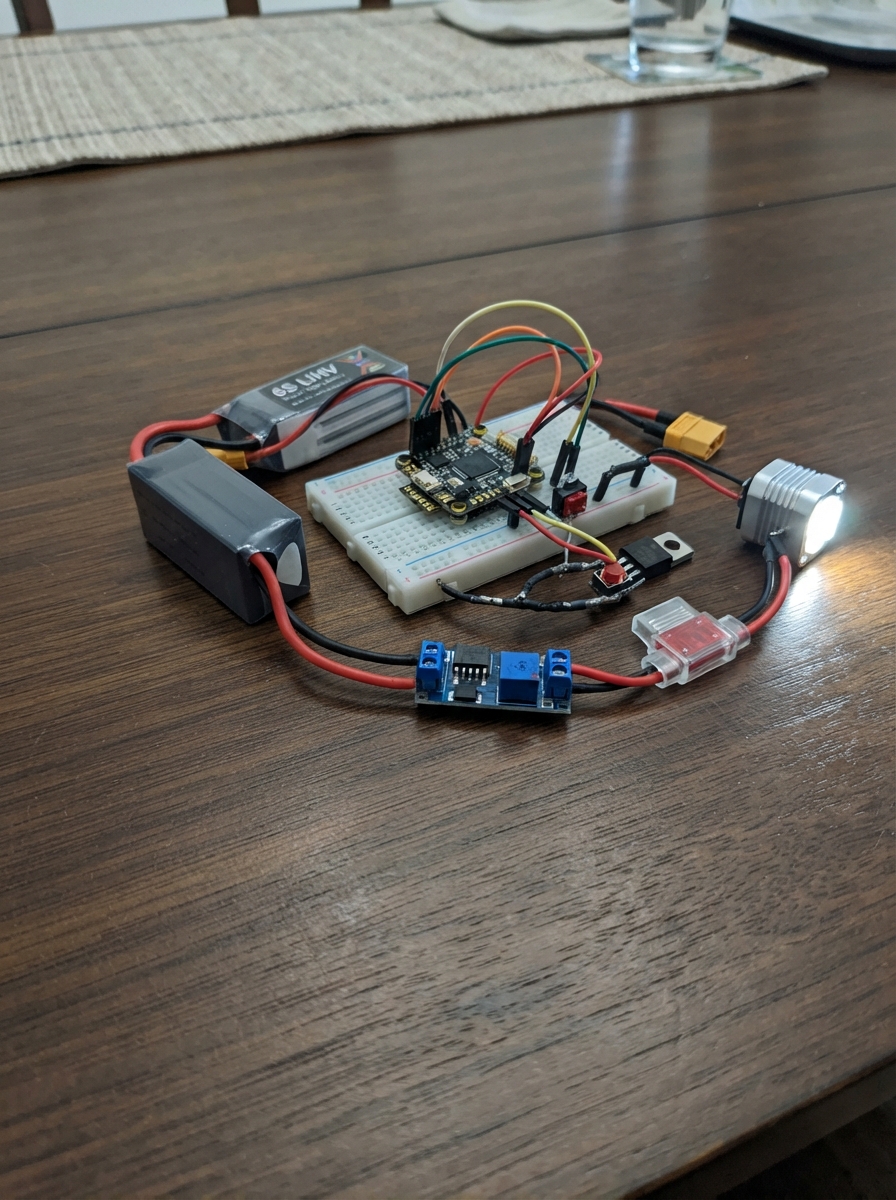
This project builds a safety-focused light controller for racing drones that integrates with Betaflight flight controllers. The system uses a Raspberry Pi Pico to monitor two radio switches and a physical safety plug, controlling a 9 V drone light through a MOSFET transistor. The controller enforces a 30-second arming delay after the safety plug is removed and requires both radio permission and an explicit light request before the lamp activates.
The guide provides a complete wiring diagram, parts list, and firmware that communicates with the flight controller via MSP protocol to read RC channel values. Assembly covers building the fused power supply, wiring the lamp switching circuit, configuring the two Betaflight radio switches, and bench-testing the system before flight. This design prioritizes safety by preventing accidental light activation during critical flight phases.
Wiring diagram

Gather all the parts
Assemble it in 6 steps
1. Keep the flight controller ports free
Leave the receiver on UART6, GPS on UART4, ESC telemetry on UART5, and UART1 exactly as they are. On the flight controller, use only the unused UART2 pads: solder FC T2 to XIAO D7/RX, FC R2 to XIAO D6/TX, FC 5V to XIAO 5V/VBUS, and FC GND to XIAO GND. Each wire’s job is: T2 → D7/RX (data), R2 → D6/TX (data), 5V → 5V/VBUS (power), and GND → GND (ground).
- Do not connect any XIAO pin directly to the 6S battery — a fully charged 6S LiHV battery can reach 26.1 V and will damage the XIAO.
- Do not use a motor pad for this project; motor pads are needed to keep the drone flying safely.
2. Build the 9 V fused lamp supply
Make the lamp power branch away from the battery connector: battery positive goes to the fuse holder IN, fuse holder OUT goes to buck converter IN+, and battery negative goes to buck converter IN-. Each wire’s job is: BAT+ → fuse IN (fault protection), fuse OUT → buck IN+ (high-voltage power), and BAT− → buck IN− (ground). Before connecting the light, use a meter and turn the converter adjustment until OUT+ to OUT− reads 9.0 V.
- Use an LM2596HVS or another converter explicitly rated for at least 30 V input. Ordinary LM2596 boards are often rated only to 40 V in theory and may not tolerate the electrical spikes on a drone.
- Never adjust or test the converter with the propellers fitted.
3. Wire the lamp switching transistor
Connect buck OUT+ to the lamp positive lead. Connect the lamp negative lead to the IRLZ44N DRAIN pin. Connect IRLZ44N SOURCE to buck OUT− and the shared ground. Solder the 100 Ω resistor between XIAO D0 and IRLZ44N GATE, then the 100 kΩ resistor from IRLZ44N GATE to ground. Each wire’s job is: OUT+ → LAMP+ (9 V power), LAMP− → DRAIN (switched return), SOURCE → OUT− (ground return), D0 → 100 Ω → GATE (on/off signal), and GATE → 100 kΩ → GND (keeps light off while starting).
- Check the exact pin order in the data sheet for the MOSFET you buy; a reversed MOSFET can short the lamp circuit or leave the lamp permanently on.
- This proof-of-concept fuse, MOSFET, and converter arrangement is limited to a 9 V lamp that draws no more than 1 A. Do not fit a larger lamp until its watts or amps are known and the power parts are redesigned.
4. Fit the bumper and removable safety plug
Use the limit switch COM and NO terminals, not NC. Connect COM to XIAO ground and NO to XIAO D2. Make the safety plug as a removable two-pin shorting link: one contact goes to XIAO ground and the other to XIAO D3. Each wire’s job is: switch COM → GND (ground), switch NO → D2 (collision signal), safety plug GND → GND (ground), and safety plug SAFE → D3 (arming signal). With the plug fitted, the light is forced off. Removing it begins the 30-second wait.
- Mount the limit switch where a frontal impact reliably presses it but ordinary vibration does not.
- Use a keyed connector or a conspicuous pull-tab for the safety plug so it cannot be confused with a battery lead.
- Keep the safety plug reachable from outside the frame. You must be able to make the lamp safe without plugging in a computer or touching a live battery lead.
5. Set the two radio switches in Betaflight
In Betaflight, enable MSP on UART2 at 115200 baud and do not enable Serial RX on UART2. Arrange your radio so AUX1 is the master permission switch and AUX2 is the intentional light switch. The XIAO reads those two values from the flight controller: it will ignore both switches for 30 seconds after the safety plug is removed, then it permits the lamp only when AUX1 is on. AUX2 turns on the light intentionally; the front switch also turns it on after a collision only while AUX1 is on.
- Confirm AUX1 and AUX2 move in Betaflight’s Receiver tab before flying. If either channel is assigned differently, the programmed channel numbers must be changed before flight.
6. Bench-test before fitting propellers
With propellers removed, insert the safety plug and power the flight controller and lamp supply. The lamp must stay off. Remove the plug and wait at least 30 seconds: the lamp must still stay off until AUX1 is on. With AUX1 on, test AUX2 and then press the limit switch; each should turn on the lamp. Turn AUX1 off or reinsert the safety plug; the lamp must turn off immediately.
- Do not test this system with propellers installed. An unexpected arming event or wiring fault can cause serious injury.
- Stop immediately if the converter, fuse holder, MOSFET, or wires become hot during the test; heat means the lamp current is higher than this proof-of-concept design allows.
Review all connections
1. Connections between "speedybee_f405_v5" and "Raspberry Pi Pico"
2. Connections between "lipo_6s" and "Raspberry Pi Pico"
3. Connections between "fuse_2a" and "Raspberry Pi Pico"
4. Connections between "buck_6s_to_9v" and "Raspberry Pi Pico"
5. Connections between "lamp_9v" and "Raspberry Pi Pico"
6. Connections between "limit_switch" and "Raspberry Pi Pico"
7. Connections between "safety_plug" and "Raspberry Pi Pico"
8. Connections between "gate_resistor" and "Raspberry Pi Pico"
9. Connections between "gate_pulldown" and "Raspberry Pi Pico"
Deploy the firmware
#include <Arduino.h>

// XIAO D6/RP2040 GPIO0 is TX and D7/RP2040 GPIO1 is RX.

// Forward declarations
uint8_t mspChecksum(uint8_t size, uint8_t command, const uint8_t *payload);
void requestRcChannels();
void readMsp();
bool channelOn(uint8_t channel);

constexpr uint8_t FC_TX_PIN = 0;
constexpr uint8_t FC_RX_PIN = 1;
constexpr uint8_t LAMP_GATE_PIN = 26;  // D0, through 100 ohm to MOSFET gate
constexpr uint8_t LIMIT_PIN = 28;      // D2, limit switch to ground when hit
constexpr uint8_t SAFETY_PIN = 29;     // D3, safety plug to ground when fitted

constexpr uint32_t MSP_BAUD = 115200;
constexpr uint32_t ARM_DELAY_MS = 30000;
constexpr uint32_t MSP_POLL_MS = 100;
constexpr uint32_t RC_TIMEOUT_MS = 500;

// Betaflight channel indexes: roll, pitch, throttle, yaw, AUX1, AUX2...
constexpr uint8_t PERMIT_CHANNEL = 4;       // AUX1: master permission
constexpr uint8_t REMOTE_LIGHT_CHANNEL = 5; // AUX2: intentional light request
constexpr uint16_t SWITCH_ON_US = 1600;

uint16_t rcChannels[16] = {0};
uint8_t rcCount = 0;
uint32_t lastRcMs = 0;
uint32_t lastPollMs = 0;
bool lastSafetyInserted = true;
uint32_t safetyRemovedMs = 0;

uint8_t mspChecksum(uint8_t size, uint8_t command, const uint8_t *payload) {
  uint8_t checksum = size ^ command;
  for (uint8_t i = 0; i < size; ++i) checksum ^= payload[i];
  return checksum;
}

void requestRcChannels() {
  const uint8_t size = 0;
  const uint8_t command = 105; // MSP_RC
  Serial1.write('$');
  Serial1.write('M');
  Serial1.write('<');
  Serial1.write(size);
  Serial1.write(command);
  Serial1.write(mspChecksum(size, command, nullptr));
}

void readMsp() {
  enum ParseState { WAIT_DOLLAR, WAIT_M, WAIT_DIR, WAIT_SIZE, WAIT_COMMAND, WAIT_PAYLOAD, WAIT_CHECKSUM };
  static ParseState state = WAIT_DOLLAR;
  static uint8_t payloadSize = 0;
  static uint8_t command = 0;
  static uint8_t payload[64];
  static uint8_t payloadIndex = 0;
  static uint8_t checksum = 0;

  while (Serial1.available()) {
    const uint8_t byteIn = Serial1.read();
    switch (state) {
      case WAIT_DOLLAR:
        if (byteIn == '$') state = WAIT_M;
        break;
      case WAIT_M:
        state = (byteIn == 'M') ? WAIT_DIR : WAIT_DOLLAR;
        break;
      case WAIT_DIR:
        state = (byteIn == '>') ? WAIT_SIZE : WAIT_DOLLAR;
        break;
      case WAIT_SIZE:
        payloadSize = byteIn;
        if (payloadSize > sizeof(payload)) { state = WAIT_DOLLAR; break; }
        checksum = byteIn;
        payloadIndex = 0;
        state = WAIT_COMMAND;
        break;
      case WAIT_COMMAND:
        command = byteIn;
        checksum ^= byteIn;
        state = (payloadSize == 0) ? WAIT_CHECKSUM : WAIT_PAYLOAD;
        break;
      case WAIT_PAYLOAD:
        payload[payloadIndex++] = byteIn;
        checksum ^= byteIn;
        if (payloadIndex >= payloadSize) state = WAIT_CHECKSUM;
        break;
      case WAIT_CHECKSUM:
        if (checksum == byteIn && command == 105 && payloadSize >= 16 && (payloadSize % 2 == 0)) {
          rcCount = min<uint8_t>(payloadSize / 2, 16);
          for (uint8_t i = 0; i < rcCount; ++i) {
            rcChannels[i] = uint16_t(payload[i * 2]) | (uint16_t(payload[i * 2 + 1]) << 8);
          }
          lastRcMs = millis();
        }
        state = WAIT_DOLLAR;
        break;
    }
  }
}

bool channelOn(uint8_t channel) {
  return channel < rcCount && rcChannels[channel] >= SWITCH_ON_US;
}

void setup() {
  pinMode(LAMP_GATE_PIN, OUTPUT);
  digitalWrite(LAMP_GATE_PIN, LOW); // Fail off before any serial traffic is accepted.
  pinMode(LIMIT_PIN, INPUT_PULLUP);
  pinMode(SAFETY_PIN, INPUT_PULLUP);
  Serial1.setTX(FC_TX_PIN);
  Serial1.setRX(FC_RX_PIN);
  Serial1.begin(MSP_BAUD);
}

void loop() {
  const uint32_t now = millis();
  readMsp();

  if (now - lastPollMs >= MSP_POLL_MS) {
    lastPollMs = now;
    requestRcChannels();
  }

  const bool safetyInserted = digitalRead(SAFETY_PIN) == LOW;
  if (safetyInserted) {
    safetyRemovedMs = 0;
  } else if (lastSafetyInserted) {
    safetyRemovedMs = now;
  }
  lastSafetyInserted = safetyInserted;

  const bool delayComplete = !safetyInserted && safetyRemovedMs != 0 && (now - safetyRemovedMs >= ARM_DELAY_MS);
  const bool rcFresh = (now - lastRcMs) <= RC_TIMEOUT_MS;
  const bool permitted = rcFresh && channelOn(PERMIT_CHANNEL);
  const bool remoteRequested = rcFresh && channelOn(REMOTE_LIGHT_CHANNEL);
  const bool collisionHit = digitalRead(LIMIT_PIN) == LOW;

  // The lamp can only run after the removed-plug delay, with fresh FC data,
  // and with AUX1 permission. AUX2 requests light manually; the bumper requests it on impact.
  const bool lampOn = delayComplete && permitted && (remoteRequested || collisionHit);
  digitalWrite(LAMP_GATE_PIN, lampOn ? HIGH : LOW);
}
Remix this project
Make it yours in one click
Open a full copy of this project in your own Schematik workspace — diagram, code, parts, and assembly steps included. Swap the sensor, add features, or redesign the whole thing with AI. The author's original stays untouched.
Related projects
RGB Button Color Controller
Raspberry Pi Pico · September 25, 2026juliaccquintanilha
Zaprojektuj Emulator Rom Dla Zx Spectrum Harlequ
Raspberry Pi Pico · September 25, 2026Piotr Chmielecki
Indoor Environment Monitor
Raspberry Pi Pico · September 24, 2026Robert M