Community project
Indoor Environment Monitor
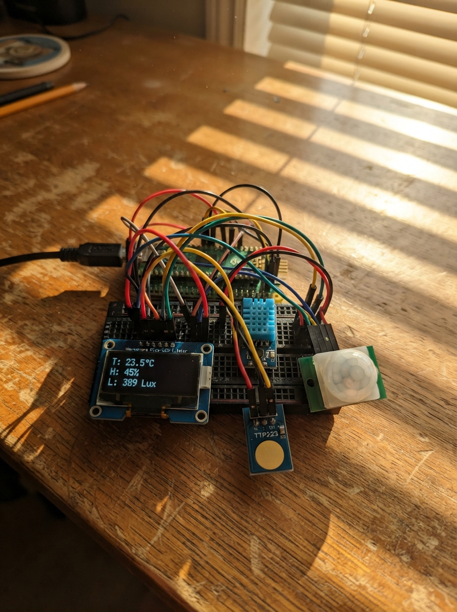
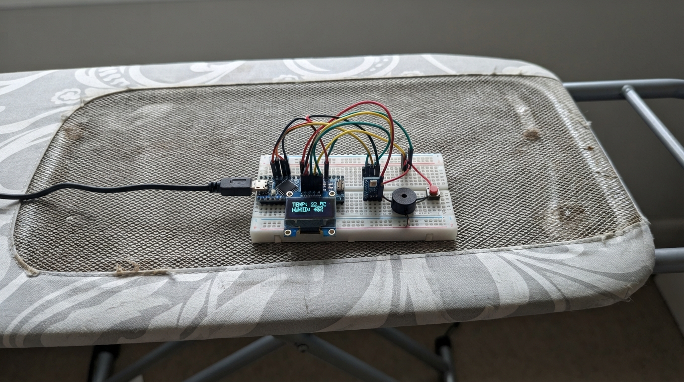
This indoor environment monitor displays real-time temperature, humidity, and motion detection on a compact 1.14-inch LCD screen. Built around a Raspberry Pi Pico, it combines a DHT11 sensor for climate data, a PIR motion sensor for activity detection, and a capacitive touch button for user interaction.
The guide provides a complete wiring diagram, parts list, and step-by-step assembly instructions. Firmware is included to read sensor data, render information on the display, and respond to touch input. Once assembled and programmed, the monitor continuously tracks indoor conditions and can trigger actions based on motion detection or manual button presses.
Wiring diagram

Gather all the parts
Assemble it in 6 steps
1. Fit the Pico LCD
Push the Waveshare Pico-LCD-1.14 straight down onto the Pico header pins, with the screen facing away from the Pico. It already uses GP8–GP13, so do not connect loose wires to those pins.
- Press evenly at both ends so no header pin bends.
- Do not force the screen if the two rows of pins are not lined up — a bent or misplaced pin can short power.
2. Place the Pico and expander
Plug the Pico into the Pico Dual Expander, then place the assembly on the breadboard so the free header pins can be reached. The expander only makes the Pico pins easier to connect; it needs no separate wiring for this project.
- Keep the LCD clear of the breadboard edge so you can read it.
- Unplug USB power before moving or plugging any module into the breadboard.
3. Wire the temperature and humidity sensor
Connect the DHT11 VCC pin to Pico 3V3 (power), GND to Pico GND (ground), and DATA to GP6 (signal). If yours is the bare four-leg DHT11 rather than a small three-pin module, use its data-sheet pin order and add a 10 kΩ resistor from DATA to 3V3.
- Keep the sensor away from the Pico's warm USB connector so it measures room air more fairly.
- Make sure VCC and GND are not swapped — swapped power can damage the sensor.
4. Wire the touch pad
Connect the TTP223 VCC to Pico 3V3 (power), GND to Pico GND (ground), and SIG to GP7 (signal). Touching its metal pad changes the LCD page.
- Use the three pins labelled VCC, GND, and SIG; the labels are usually printed beside the header.
- Do not connect the touch module to 5 V for this project, because its signal would then be too high for the Pico input.
5. Wire the motion detector
Connect the HC-SR501 VCC to Pico VBUS/5V (power from USB), GND to Pico GND (ground), and OUT to GP14 (signal). Aim the white dome toward the area you want to watch.
- After USB power is applied, wait about a minute for the motion detector to settle before judging its response.
- All modules must share the same GND connection or their signals cannot be read reliably.
6. Power and test the monitor
Check each wire once, then plug the Pico into USB. The LCD should show the room monitor after deployment; touch the TTP223 pad to change to the motion-status page.
- The DHT11 updates about every two seconds, so give the numbers a moment to appear.
- If the LCD stays blank, unplug USB first and check that the LCD is fully seated, rather than reseating it while powered.
Review all connections
1. Connections between "pico_lcd_114" and "Raspberry Pi Pico"
2. Connections between "dht11_1" and "Raspberry Pi Pico"
3. Connections between "touch_1" and "Raspberry Pi Pico"
4. Connections between "pir_1" and "Raspberry Pi Pico"
Deploy the firmware
#include <Arduino.h>
#include <SPI.h>

// The physical Pico uses SPI1. The browser simulator supplies only SPI.
// This fallback is excluded from Raspberry Pi Pico firmware.
#if !defined(ARDUINO_ARCH_RP2040)
typedef uint8_t BitOrder;
#endif

#include <Adafruit_GFX.h>
#include <Adafruit_ST7789.h>
#include <DHT.h>


// Forward declarations
void clearContent();
void drawHeader(const char *title);
void drawMainPage();
void drawStatusPage();
void drawCurrentPage();

constexpr uint8_t TFT_DC = 8;
constexpr uint8_t TFT_CS = 9;
constexpr uint8_t TFT_SCK = 10;
constexpr uint8_t TFT_MOSI = 11;
constexpr uint8_t TFT_RST = 12;
constexpr uint8_t TFT_BL = 13;
constexpr uint8_t DHT_PIN = 6;
constexpr uint8_t TOUCH_PIN = 7;
constexpr uint8_t PIR_PIN = 14;
constexpr uint8_t DHT_TYPE = DHT11;

#if defined(ARDUINO_ARCH_RP2040)
Adafruit_ST7789 tft(&SPI1, TFT_CS, TFT_DC, TFT_RST);
#else
Adafruit_ST7789 tft(&SPI, TFT_CS, TFT_DC, TFT_RST);
#endif
DHT dht(DHT_PIN, DHT_TYPE);

float temperatureC = NAN;
float humidity = NAN;
bool motionSeen = false;
bool statusPage = false;
bool lastTouch = false;
unsigned long lastSensorRead = 0;
unsigned long lastTouchChange = 0;

void clearContent() {
  tft.fillRect(0, 24, 240, 111, ST77XX_BLACK);
}

void drawHeader(const char *title) {
  tft.fillRect(0, 0, 240, 24, ST77XX_BLUE);
  tft.setTextColor(ST77XX_WHITE, ST77XX_BLUE);
  tft.setTextSize(2);
  tft.setCursor(6, 5);
  tft.print(title);
}

void drawMainPage() {
  drawHeader("ROOM MONITOR");
  clearContent();
  tft.setTextSize(2);
  tft.setTextColor(ST77XX_CYAN, ST77XX_BLACK);
  tft.setCursor(8, 36);
  tft.print("Temperature");
  tft.setTextColor(ST77XX_WHITE, ST77XX_BLACK);
  tft.setCursor(8, 57);
  if (isnan(temperatureC)) tft.print("Waiting...");
  else { tft.print(temperatureC, 1); tft.print(" C"); }

  tft.setTextColor(ST77XX_GREEN, ST77XX_BLACK);
  tft.setCursor(8, 82);
  tft.print("Humidity");
  tft.setTextColor(ST77XX_WHITE, ST77XX_BLACK);
  tft.setCursor(8, 103);
  if (isnan(humidity)) tft.print("Waiting...");
  else { tft.print(humidity, 0); tft.print(" %"); }

  tft.setTextSize(1);
  tft.setTextColor(ST77XX_YELLOW, ST77XX_BLACK);
  tft.setCursor(8, 122);
  tft.print("Touch pad: motion status");
}

void drawStatusPage() {
  drawHeader("SAFETY STATUS");
  clearContent();
  tft.setTextSize(2);
  tft.setCursor(8, 42);
  if (motionSeen) {
    tft.setTextColor(ST77XX_RED, ST77XX_BLACK);
    tft.print("MOTION SEEN");
    tft.setTextSize(1);
    tft.setTextColor(ST77XX_WHITE, ST77XX_BLACK);
    tft.setCursor(8, 76);
    tft.print("Restart Pico to clear alert");
  } else {
    tft.setTextColor(ST77XX_GREEN, ST77XX_BLACK);
    tft.print("NO MOTION YET");
    tft.setTextSize(1);
    tft.setTextColor(ST77XX_WHITE, ST77XX_BLACK);
    tft.setCursor(8, 76);
    tft.print("PIR is watching the room");
  }
  tft.setTextColor(ST77XX_YELLOW, ST77XX_BLACK);
  tft.setCursor(8, 122);
  tft.print("Touch pad: main screen");
}

void drawCurrentPage() {
  if (statusPage) drawStatusPage();
  else drawMainPage();
}

void setup() {
  pinMode(TFT_BL, OUTPUT);
  digitalWrite(TFT_BL, HIGH);
  pinMode(TOUCH_PIN, INPUT);
  pinMode(PIR_PIN, INPUT);

#if defined(ARDUINO_ARCH_RP2040)
  SPI1.setSCK(TFT_SCK);
  SPI1.setTX(TFT_MOSI);
  SPI1.begin();
#else
  SPI.begin();
#endif
  tft.init(135, 240);
  tft.setRotation(3);
  tft.fillScreen(ST77XX_BLACK);

  dht.begin();
  drawCurrentPage();
}

void loop() {
  const unsigned long now = millis();

  if (digitalRead(PIR_PIN) == HIGH && !motionSeen) {
    motionSeen = true;
    if (statusPage) drawStatusPage();
  }

  bool touch = digitalRead(TOUCH_PIN) == HIGH;
  if (touch && !lastTouch && now - lastTouchChange > 150) {
    statusPage = !statusPage;
    lastTouchChange = now;
    drawCurrentPage();
  }
  lastTouch = touch;

  if (now - lastSensorRead >= 2000 || lastSensorRead == 0) {
    lastSensorRead = now;
    float newHumidity = dht.readHumidity();
    float newTemperature = dht.readTemperature();
    if (!isnan(newHumidity) && !isnan(newTemperature)) {
      bool changed = isnan(temperatureC) || isnan(humidity) ||
                     newTemperature != temperatureC || newHumidity != humidity;
      temperatureC = newTemperature;
      humidity = newHumidity;
      if (changed && !statusPage) drawMainPage();
    }
  }
}
Remix this project
Make it yours in one click
Open a full copy of this project in your own Schematik workspace — diagram, code, parts, and assembly steps included. Swap the sensor, add features, or redesign the whole thing with AI. The author's original stays untouched.