Community project
Dual-Mode Robotic Arm
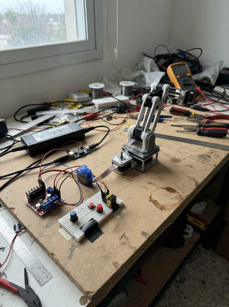
This dual-mode robotic arm combines manual joystick control with autonomous pick-and-place operation. Built around an Arduino Uno, the arm uses a NEMA 17 stepper motor for base rotation, two SG90 servos for arm articulation and gripper control, and an L298N motor driver to manage the stepper coils. The guide provides a complete wiring diagram, parts list, firmware with both manual and automatic modes, and step-by-step assembly instructions.
Readers will learn how to wire the stepper motor with its controller, integrate analog potentiometers for smooth manual positioning, and implement a state machine that automates a full pick-and-place cycle. The firmware includes homing logic, deadband filtering for joystick inputs, and configurable step counts to match arm geometry. Assembly follows a safe sequence: mechanical setup first, power supply calibration, then electrical connections with testing and travel calibration.
Wiring diagram

Gather all the parts
Assemble it in 8 steps
1. Monte la mecánica sin alimentar
Fije el NEMA 17 en la base giratoria y coloque el final de carrera para que la base lo pulse suavemente en su posición de origen, sin aplastarlo. Monte el servo de articulación y el servo de pinza con los brazos mecánicos sin forzar sus ejes.
- Deje la pinza vacía durante las primeras pruebas.
- El interruptor debe activarse antes de que una pieza rígida llegue a su tope.
- No conecte todavía la fuente de 12 V: un brazo mal alineado puede moverse de golpe al recibir energía.
2. Ajuste el convertidor a 5 V
Con la fuente de 12 V desconectada del Arduino y de los servos, conecte la entrada del convertidor a la fuente: +12V de fuente_12v a VIN+ de convertidor_5v (alimentación) y GND de fuente_12v a VIN- de convertidor_5v (retorno). Mida la salida y ajuste el tornillo del convertidor hasta obtener 5.0 V entre VOUT+ y VOUT-.
- Use un multímetro; este ajuste se hace una sola vez antes de enchufar el Arduino.
- Use cables suficientemente gruesos para la alimentación de los motores.
- No conecte una salida sin medir a los servos ni al Arduino: más de 5 V puede dañarlos.
3. Conecte el NEMA y su controlador
Conecte una pareja de cables de la misma bobina del NEMA a OUT1 y OUT2 del l298n_1, y la otra pareja a OUT3 y OUT4: OUT1 a A+ (bobina A), OUT2 a A- (bobina A), OUT3 a B+ (bobina B), OUT4 a B- (bobina B). Conecte +12V de fuente_12v a VS del l298n_1 (potencia del motor) y GND de fuente_12v a GND del l298n_1 (retorno). Lleve IN1 a D2, IN2 a D3, IN3 a D4 e IN4 a D5 del Arduino Uno (órdenes de giro). Lleve también el pin 5V del l298n_1 al carril de 5 V (alimentación lógica).
- Para identificar una bobina, dos cables que dan una resistencia baja entre sí pertenecen a la misma pareja.
- Si el motor vibra sin girar, apague todo y revise que las parejas de bobina no estén mezcladas.
- El L298N se calienta y no regula la corriente como un A4988; no use este montaje con un NEMA 17 que supere 1 A por bobina ni lo deje bloqueado.
4. Haga el carril común de 5 V y tierra
Conecte VOUT+ de convertidor_5v al carril de 5 V (alimentación) y VOUT- al carril GND (retorno). Conecte el pin 5V del Arduino Uno a ese carril de 5 V (alimentación) y un pin GND del Arduino al carril GND (retorno). Todos los GND de los servos, mandos, controlador y Arduino deben quedar unidos; esta tierra común permite que las señales tengan la misma referencia.
- Use una regleta de distribución o una protoboard solo para las señales; los cables de motor y alimentación conviene llevarlos por una regleta de tornillos.
- No alimente los servos desde el pin 5V USB del Arduino: sus picos de corriente pueden reiniciar o dañar la placa.
5. Conecte los dos servos
En servo_articulacion conecte VCC al carril de 5 V (alimentación), GND al carril GND (retorno) y SIGNAL a D9 (orden de posición). En servo_pinza conecte VCC al carril de 5 V (alimentación), GND al carril GND (retorno) y SIGNAL a D10 (orden de abrir y cerrar).
- En muchos servos el cable rojo es VCC, marrón o negro es GND y naranja/amarillo es SIGNAL; confirme los colores del suyo.
- No intercambie rojo y negro: invertir la alimentación puede dañar el servo.
6. Conecte los tres mandos manuales
Para cada potenciómetro conecte VCC al carril de 5 V (alimentación) y GND al carril GND (retorno). Conecte el terminal central WIPER de pot_base a A0 (mando de giro de la base), el de pot_articulacion a A1 (posición del brazo) y el de pot_pinza a A2 (apertura de la pinza).
- El terminal central siempre es el que envía la orden variable.
- Si un mando gira al revés de lo esperado, apague el sistema e intercambie sus dos terminales exteriores.
- Mantenga los cables de los potenciómetros alejados de los cables del NEMA para reducir movimientos erráticos.
7. Conecte los botones y el origen
Conecte un lado de boton_modo a GND y su otro lado a D6 (cambia entre manual y automático). Conecte un lado de boton_ciclo a GND y su otro lado a D7 (inicia el recorrido automático). En final_carrera_origen conecte COM a GND y NO a D8 (avisa que la base llegó a origen).
- Los botones no necesitan resistencias extra porque el programa usa la resistencia interna del Arduino.
- Compruebe que D8 lee el cambio al pulsar el final de carrera antes de dejar que el brazo haga un ciclo solo.
- Use los contactos COM y NO del final de carrera; usar NC con este programa haría que el origen parezca pulsado todo el tiempo.
8. Pruebe primero y calibre el recorrido
Con la pinza vacía, encienda la fuente y coloque los tres mandos en una zona segura. En modo manual, el mando de base gira a un lado u otro desde su centro; los otros dos mandos colocan brazo y pinza. Pulse boton_modo para entrar en automático y boton_ciclo para iniciar: la base buscará primero el final de carrera. Cambie AUTO_PICK_STEPS y AUTO_DROP_STEPS en el código si las posiciones de recoger y dejar no coinciden con su estructura.
- El recorrido automático se detiene si no encuentra el interruptor de origen en 15 segundos.
- Mantenga la mano cerca del interruptor de la fuente durante la primera prueba.
- No ponga dedos dentro de la pinza ni cerca de la base mientras el modo automático está activo: el brazo puede pellizcar o girar inesperadamente.
Review all connections
1. Connections between "fuente_12v" and "Arduino"
2. Connections between "convertidor_5v" and "Arduino"
3. Connections between "l298n_1" and "Arduino"
4. Connections between "servo_articulacion" and "Arduino"
5. Connections between "servo_pinza" and "Arduino"
6. Connections between "pot_base" and "Arduino"
7. Connections between "pot_articulacion" and "Arduino"
8. Connections between "pot_pinza" and "Arduino"
9. Connections between "boton_modo" and "Arduino"
10. Connections between "boton_ciclo" and "Arduino"
11. Connections between "final_carrera_origen" and "Arduino"
Deploy the firmware
#include <Arduino.h>
#include <Servo.h>

// L298N: las dos salidas OUT1/OUT2 manejan una bobina y OUT3/OUT4 la otra.
const uint8_t L298_IN1 = 2;
const uint8_t L298_IN2 = 3;
const uint8_t L298_IN3 = 4;
const uint8_t L298_IN4 = 5;
const uint8_t MODE_BUTTON_PIN = 6;
const uint8_t CYCLE_BUTTON_PIN = 7;
const uint8_t HOME_SWITCH_PIN = 8;
const uint8_t ARM_SERVO_PIN = 9;
const uint8_t GRIPPER_SERVO_PIN = 10;
const uint8_t BASE_POT_PIN = A0;
const uint8_t ARM_POT_PIN = A1;
const uint8_t GRIPPER_POT_PIN = A2;

const unsigned long STEP_INTERVAL_MS = 8;
const unsigned long SERVO_SETTLE_MS = 650;
const unsigned long HOME_TIMEOUT_MS = 15000;
const int MANUAL_DEADBAND = 70;
const int AUTO_PICK_STEPS = 110;  // Ajustar a la geometria real del brazo.
const int AUTO_DROP_STEPS = 220;  // Debe ser el doble de AUTO_PICK_STEPS.

Servo servoBrazo;
Servo servoPinza;

const uint8_t coilPattern[4][4] = {
  {HIGH, LOW, HIGH, LOW},
  {LOW, HIGH, HIGH, LOW},
  {LOW, HIGH, LOW, HIGH},
  {HIGH, LOW, LOW, HIGH}
};

int phaseIndex = 0;
unsigned long lastStepMs = 0;
unsigned long lastButtonMs = 0;
bool automaticMode = false;
bool lastModeReading = HIGH;
bool lastCycleReading = HIGH;

// Estados del recorrido: busca origen, recoge, gira, deja y vuelve a origen.
enum AutoState {
  AUTO_IDLE,
  AUTO_HOME,
  AUTO_GO_PICK,
  AUTO_LOWER_PICK,
  AUTO_CLOSE_GRIPPER,
  AUTO_LIFT_PICK,
  AUTO_GO_DROP,
  AUTO_LOWER_DROP,
  AUTO_OPEN_GRIPPER,
  AUTO_LIFT_DROP,
  AUTO_RETURN_HOME
};

AutoState autoState = AUTO_IDLE;
int stepsRemaining = 0;
unsigned long stateStartedMs = 0;

void applyCoils() {
  digitalWrite(L298_IN1, coilPattern[phaseIndex][0]);
  digitalWrite(L298_IN2, coilPattern[phaseIndex][1]);
  digitalWrite(L298_IN3, coilPattern[phaseIndex][2]);
  digitalWrite(L298_IN4, coilPattern[phaseIndex][3]);
}

void stepBase(int direction) {
  phaseIndex += (direction > 0) ? 1 : -1;
  if (phaseIndex > 3) phaseIndex = 0;
  if (phaseIndex < 0) phaseIndex = 3;
  applyCoils();
}

bool timeForStep() {
  unsigned long now = millis();
  if (now - lastStepMs < STEP_INTERVAL_MS) return false;
  lastStepMs = now;
  return true;
}

bool homePressed() {
  // COM a GND y NO a D8: pulsado equivale a LOW.
  return digitalRead(HOME_SWITCH_PIN) == LOW;
}

void enterState(AutoState nextState) {
  autoState = nextState;
  stateStartedMs = millis();

  switch (autoState) {
    case AUTO_HOME:
      servoBrazo.write(70);
      servoPinza.write(25);       // pinza abierta
      break;
    case AUTO_GO_PICK:
      stepsRemaining = AUTO_PICK_STEPS;
      break;
    case AUTO_LOWER_PICK:
      servoBrazo.write(120);
      break;
    case AUTO_CLOSE_GRIPPER:
      servoPinza.write(78);       // cerrar sin forzar la pinza
      break;
    case AUTO_LIFT_PICK:
      servoBrazo.write(70);
      break;
    case AUTO_GO_DROP:
      stepsRemaining = AUTO_DROP_STEPS;
      break;
    case AUTO_LOWER_DROP:
      servoBrazo.write(118);
      break;
    case AUTO_OPEN_GRIPPER:
      servoPinza.write(25);
      break;
    case AUTO_LIFT_DROP:
      servoBrazo.write(70);
      break;
    case AUTO_RETURN_HOME:
      break;
    case AUTO_IDLE:
      break;
  }
}

void startAutomaticCycle() {
  enterState(AUTO_HOME);
}

void runManual() {
  int baseValue = analogRead(BASE_POT_PIN);
  int armAngle = map(analogRead(ARM_POT_PIN), 0, 1023, 20, 160);
  int gripperAngle = map(analogRead(GRIPPER_POT_PIN), 0, 1023, 20, 85);

  servoBrazo.write(armAngle);
  servoPinza.write(gripperAngle);

  int offset = baseValue - 512;
  if (abs(offset) > MANUAL_DEADBAND && timeForStep()) {
    stepBase(offset > 0 ? 1 : -1);
  }
}

bool runStepsForward() {
  if (stepsRemaining <= 0) return true;
  if (timeForStep()) {
    stepBase(1);
    --stepsRemaining;
  }
  return stepsRemaining <= 0;
}

void runAutomatic() {
  unsigned long elapsed = millis() - stateStartedMs;

  switch (autoState) {
    case AUTO_HOME:
      if (homePressed()) {
        phaseIndex = 0;
        applyCoils();
        enterState(AUTO_GO_PICK);
      } else if (elapsed >= HOME_TIMEOUT_MS) {
        // Si el interruptor no se alcanza, detiene el ciclo en vez de golpear el mecanismo.
        enterState(AUTO_IDLE);
      } else if (timeForStep()) {
        stepBase(-1);
      }
      break;

    case AUTO_GO_PICK:
      if (runStepsForward()) enterState(AUTO_LOWER_PICK);
      break;
    case AUTO_LOWER_PICK:
      if (elapsed >= SERVO_SETTLE_MS) enterState(AUTO_CLOSE_GRIPPER);
      break;
    case AUTO_CLOSE_GRIPPER:
      if (elapsed >= SERVO_SETTLE_MS) enterState(AUTO_LIFT_PICK);
      break;
    case AUTO_LIFT_PICK:
      if (elapsed >= SERVO_SETTLE_MS) enterState(AUTO_GO_DROP);
      break;
    case AUTO_GO_DROP:
      if (runStepsForward()) enterState(AUTO_LOWER_DROP);
      break;
    case AUTO_LOWER_DROP:
      if (elapsed >= SERVO_SETTLE_MS) enterState(AUTO_OPEN_GRIPPER);
      break;
    case AUTO_OPEN_GRIPPER:
      if (elapsed >= SERVO_SETTLE_MS) enterState(AUTO_LIFT_DROP);
      break;
    case AUTO_LIFT_DROP:
      if (elapsed >= SERVO_SETTLE_MS) enterState(AUTO_RETURN_HOME);
      break;
    case AUTO_RETURN_HOME:
      if (homePressed()) {
        enterState(AUTO_IDLE);
      } else if (elapsed >= HOME_TIMEOUT_MS) {
        enterState(AUTO_IDLE);
      } else if (timeForStep()) {
        stepBase(-1);
      }
      break;
    case AUTO_IDLE:
      break;
  }
}

void readButtons() {
  bool modeReading = digitalRead(MODE_BUTTON_PIN);
  bool cycleReading = digitalRead(CYCLE_BUTTON_PIN);
  unsigned long now = millis();

  if (now - lastButtonMs >= 40) {
    if (lastModeReading == HIGH && modeReading == LOW) {
      automaticMode = !automaticMode;
      if (!automaticMode) enterState(AUTO_IDLE);
      lastButtonMs = now;
    }

    if (lastCycleReading == HIGH && cycleReading == LOW && automaticMode && autoState == AUTO_IDLE) {
      startAutomaticCycle();
      lastButtonMs = now;
    }
  }

  lastModeReading = modeReading;
  lastCycleReading = cycleReading;
}

void setup() {
  pinMode(L298_IN1, OUTPUT);
  pinMode(L298_IN2, OUTPUT);
  pinMode(L298_IN3, OUTPUT);
  pinMode(L298_IN4, OUTPUT);
  pinMode(MODE_BUTTON_PIN, INPUT_PULLUP);
  pinMode(CYCLE_BUTTON_PIN, INPUT_PULLUP);
  pinMode(HOME_SWITCH_PIN, INPUT_PULLUP);

  servoBrazo.attach(ARM_SERVO_PIN);
  servoPinza.attach(GRIPPER_SERVO_PIN);
  servoBrazo.write(70);
  servoPinza.write(25);
  applyCoils();
}

void loop() {
  readButtons();

  if (automaticMode) {
    runAutomatic();
  } else {
    runManual();
  }

  delay(1);
}
Remix this project
Make it yours in one click
Open a full copy of this project in your own Schematik workspace — diagram, code, parts, and assembly steps included. Swap the sensor, add features, or redesign the whole thing with AI. The author's original stays untouched.