Community project
OLED RTC Clock
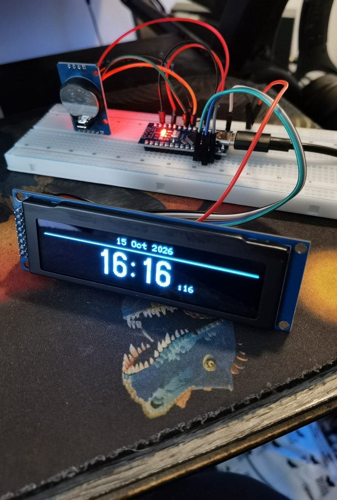
This project builds a precise desk clock that displays the current time and date on a large OLED screen. The DS3231 real-time clock module keeps accurate time even when power is disconnected, thanks to its coin-cell battery backup, while the 256x64 pixel OLED display renders crisp, readable digits and date information.
The guide provides a complete wiring diagram, parts list, and step-by-step assembly instructions for connecting the RTC and OLED modules to an Arduino Uno. Included firmware handles time synchronization, display updates, and screen rendering, allowing builders to have a working clock within an hour.
Wiring diagram

Gather all the parts
Assemble it in 4 steps
1. Keep power disconnected while wiring
Place the Nano, DS3231, and OLED on the bench. Leave the Nano USB cable unplugged until every wire has been checked.
- The OLED header numbering starts with VSS at pin 1 and VCC_IN/VBAT at pin 2.
- Do not connect power while moving wires; an accidental connection between 5V and GND can damage the board or USB port.
2. Connect power to the clock parts
Connect DS3231 VCC to Nano 5V and DS3231 GND to Nano GND. Connect OLED VCC_IN or VBAT pin 2 to Nano 5V and OLED VSS pin 1 to Nano GND. Fit a CR2032 into the DS3231 holder with its marked positive side facing upward.
- DS3231 VCC → Nano 5V (power); DS3231 GND → Nano GND (ground).
- OLED VCC_IN/VBAT pin 2 → Nano 5V (power); OLED VSS pin 1 → Nano GND (ground).
- Make sure OLED VCC_IN/VBAT and VSS are not swapped — swapped power can damage the screen.
3. Wire the time and screen signals
Connect DS3231 SDA to Nano A4 and SCL to Nano A5. Connect OLED SCLK pin 4 to Nano D13, SDIN pin 5 to D11, /CS pin 16 to D10, /DC pin 14 to D9, and /Reset pin 15 to D8.
- SDA → A4 (data); SCL → A5 (clock).
- SCLK → D13 (clock); SDIN → D11 (picture data); /CS → D10 (screen select); /DC → D9 (command/data); /Reset → D8 (reset).
- Follow the display’s printed pin numbers rather than its physical orientation; connecting a signal to a power pin can damage the display.
4. Power and deploy the clock
Plug the Nano into a USB power cable. The cable powers the Nano, RTC, and OLED. Press Deploy in Schematik to put the clock firmware on the Nano.
- The DS3231 coin cell keeps the time when the Nano USB cable is unplugged.
- The Nano’s USB socket is the only power connection needed for this version.
- Do not connect an external battery or a separate 5 V supply to the Nano while it is powered by USB.
Review all connections
1. Connections between "rtc_ds3231" and "Arduino"
2. Connections between "oled_ssd1322" and "Arduino"
Deploy the firmware
#include <Arduino.h>
#include <Wire.h>
#include <EEPROM.h>
#include <RTClib.h>
#include <U8g2lib.h>

const uint8_t OLED_CS_PIN = 10;
const uint8_t OLED_DC_PIN = 9;
const uint8_t OLED_RESET_PIN = 8;

RTC_DS3231 rtc;

// Nano hardware SPI: D13 = SCLK and D11 = MOSI / the OLED's SDIN pin.
// The page-buffer constructor fits in the Nano's available memory.
U8G2_SSD1322_NHD_256X64_1_4W_HW_SPI oled(
  U8G2_R0, OLED_CS_PIN, OLED_DC_PIN, OLED_RESET_PIN);

const char *const MONTH_NAMES[] = {
  "Jan", "Feb", "Mar", "Apr", "May", "Jun",
  "Jul", "Aug", "Sep", "Oct", "Nov", "Dec"
};

void showMessage(const char *message) {
  oled.firstPage();
  do {
    oled.setFont(u8g2_font_6x12_tf);
    const int16_t x = (256 - oled.getStrWidth(message)) / 2;
    oled.drawStr(x, 36, message);
  } while (oled.nextPage());
}

void drawClock(const DateTime &now) {
  char dateText[18];
  char timeText[6];
  char secondsText[4];

  snprintf(dateText, sizeof(dateText), "%02d %s %04d",
           now.day(), MONTH_NAMES[now.month() - 1], now.year());
  snprintf(timeText, sizeof(timeText), "%02d:%02d",
           now.hour(), now.minute());
  snprintf(secondsText, sizeof(secondsText), ":%02d", now.second());

  oled.firstPage();
  do {
    oled.setDrawColor(1);

    oled.setFont(u8g2_font_6x12_tf);
    oled.drawStr((256 - oled.getStrWidth(dateText)) / 2, 12, dateText);
    oled.drawHLine(4, 17, 248);

    oled.setFont(u8g2_font_logisoso32_tn);
    const uint16_t timeWidth = oled.getStrWidth(timeText);

    oled.setFont(u8g2_font_6x12_tf);
    const uint16_t secondsWidth = oled.getStrWidth(secondsText);
    const int16_t timeX = (256 - timeWidth - secondsWidth - 3) / 2;

    oled.setFont(u8g2_font_logisoso32_tn);
    oled.drawStr(timeX, 55, timeText);

    oled.setFont(u8g2_font_6x12_tf);
    oled.drawStr(timeX + timeWidth + 3, 55, secondsText);
  } while (oled.nextPage());
}

void setup() {
  Wire.begin();
  oled.begin();

  if (!rtc.begin()) {
    showMessage("DS3231 not found");
    while (true) {
      delay(1000);
    }
  }

  // Initialise the replacement RTC once to the supplied UK local time.
  // The marker prevents normal restarts from setting it again.
  const uint32_t initialiseMarker = 0x4B544332UL;
  uint32_t savedMarker = 0;
  EEPROM.get(0, savedMarker);
  if (savedMarker != initialiseMarker) {
    rtc.adjust(DateTime(2026, 10, 15, 16, 8, 0));
    EEPROM.put(0, initialiseMarker);
  }

  // Apply the requested correction exactly once, then remember that it ran.
  const uint32_t correctionMarker = 0x4B544333UL;
  uint32_t savedCorrectionMarker = 0;
  EEPROM.get(4, savedCorrectionMarker);
  if (savedCorrectionMarker != correctionMarker) {
    rtc.adjust(rtc.now() + TimeSpan(0, 0, 1, 25));
    EEPROM.put(4, correctionMarker);
  }
}

void loop() {
  static uint8_t shownSecond = 255;
  const DateTime now = rtc.now();

  if (now.second() != shownSecond) {
    shownSecond = now.second();
    drawClock(now);
  }
}
Remix this project
Make it yours in one click
Open a full copy of this project in your own Schematik workspace — diagram, code, parts, and assembly steps included. Swap the sensor, add features, or redesign the whole thing with AI. The author's original stays untouched.