Community project
ESP32 Climate Dashboard
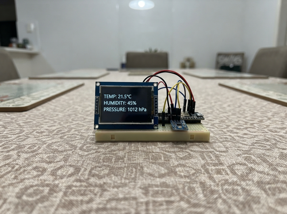
This project builds a real-time climate monitor using an ESP32 microcontroller, a BME280 environmental sensor, and a 2.4-inch ILI9341 display. The sensor reads temperature, humidity, and barometric pressure while the display presents live readings in a clean dashboard layout that updates every two seconds.
The guide provides a complete wiring diagram, parts list, and step-by-step assembly instructions designed for a compact, breadboard-free build. Firmware is included and ready to flash, with all pin configurations clearly documented for easy customization.
Wiring diagram

Gather all the parts
Assemble it in 4 steps
1. Skip the breadboard and arrange the modules
Use short female-to-female jumper wires, so the ESP32, BME280, and TFT connect directly without a breadboard. Lay the ESP32 in the middle with its USB connector facing down, the BME280 to its left, and the TFT to its right. Keep the BME280 a few centimetres from the ESP32 because the ESP32 becomes warm and can make the temperature reading slightly high.
- If you need the project held in one piece for the demo, put all three modules on a small piece of cardboard or acrylic and secure them with removable tape.
- A 170-point mini breadboard is optional only as a holder; it is not needed for electrical connections.
- Do not let the loose metal ends of jumper wires touch each other while USB power is connected; that can short the ESP32 power supply.
2. Connect the four short sensor wires
Run four short wires straight from the ESP32's left side to the BME280: BME280 VCC → ESP32 3V3 (power); BME280 GND → ESP32 GND (ground); BME280 SDA or SDI → ESP32 GPIO21 (data); BME280 SCL or SCK → ESP32 GPIO22 (timing).
- Use red for VCC, black for GND, and two other colors for SDA and SCL so each connection is easy to trace.
- The BME280 breakout already has the small parts needed for its shared data wires, so do not add resistors.
- Make sure VCC and GND are not swapped — swapped power can damage the sensor.
3. Connect the screen in one tidy bundle
Run the TFT wires in parallel from the ESP32's right side to the screen: TFT VCC → ESP32 3V3 (power); TFT GND → ESP32 GND (ground); TFT MOSI or SDI → GPIO23 (picture data); TFT SCK or CLK → GPIO18 (timing); TFT CS → GPIO27 (screen select); TFT DC, A0, or RS → GPIO26 (command or picture select); TFT RST or RESET → GPIO25 (screen reset).
- Use the shortest jumper wires that reach without pulling on the pins; 10 cm wires usually make a neat compact demo.
- Leave TFT MISO and all touch-related pins disconnected.
- Place the power wires at the outside of the bundle and keep the five signal wires beside each other to avoid crossings.
- Use a TFT specified for 3.3V logic. A screen that expects 5V signal wires can fail or damage the ESP32.
4. Check the compact wiring before power
Before connecting USB, verify that each module has exactly one VCC wire to ESP32 3V3 and one GND wire to ESP32 GND. Then follow each remaining wire from its printed module label to the GPIO named in the previous steps. Plug the ESP32 into USB only after this check.
- For travel, unplug USB first, then wrap a rubber band loosely around the wire bundle; do not bend the TFT pins sharply.
- If a module has uninstalled header pins, solder its headers first. Loose header contact is a common cause of a blank screen or missing sensor reading.
- Do not use the ESP32 5V/VIN pin for either module in this project; both modules are powered from 3V3.
Review all connections
1. Connections between "bme280_1" and "ESP32"
2. Connections between "ili9341_tft_1" and "ESP32"
Deploy the firmware
#include <Arduino.h>
#include <Wire.h>
#include <SPI.h>
#include <Adafruit_GFX.h>
#include <Adafruit_ILI9341.h>
#include <Adafruit_BME280.h>


// Forward declarations
void drawLabel(const char *label, int y);
void drawStaticScreen();
void drawValue(int y, const String &value, uint16_t color);
void showSensorError();
void updateDashboard();

constexpr int TFT_MOSI_PIN = 23;
constexpr int TFT_SCK_PIN = 18;
constexpr int TFT_CS_PIN = 27;
constexpr int TFT_DC_PIN = 26;
constexpr int TFT_RST_PIN = 25;
constexpr int BME_SDA_PIN = 21;
constexpr int BME_SCL_PIN = 22;
constexpr unsigned long UPDATE_INTERVAL_MS = 2000;

// RGB565 colors defined locally so the dashboard works with both the real
// ILI9341 library and the browser simulator compatibility layer.
constexpr uint16_t COLOR_LIGHT_GREY = 0xC618;
constexpr uint16_t COLOR_DARK_CYAN = 0x03EF;
constexpr uint16_t COLOR_DARK_GREY = 0x7BEF;
constexpr uint16_t COLOR_ORANGE = 0xFD20;

Adafruit_ILI9341 tft(TFT_CS_PIN, TFT_DC_PIN, TFT_RST_PIN);
Adafruit_BME280 bme;

bool sensorReady = false;
unsigned long lastUpdateMs = 0;

void drawLabel(const char *label, int y) {
  tft.setTextSize(2);
  tft.setTextColor(COLOR_LIGHT_GREY, ILI9341_BLACK);
  tft.setCursor(12, y);
  tft.print(label);
}

void drawStaticScreen() {
  tft.fillScreen(ILI9341_BLACK);
  tft.setTextSize(2);
  tft.setTextColor(ILI9341_CYAN, ILI9341_BLACK);
  tft.setCursor(12, 10);
  tft.print("CLIMATE MONITOR");
  tft.drawFastHLine(10, 34, 220, COLOR_DARK_CYAN);
  drawLabel("Temp", 52);
  drawLabel("Humidity", 92);
  drawLabel("Pressure", 132);
  tft.drawFastHLine(10, 170, 220, COLOR_DARK_GREY);
  drawLabel("Comfort", 184);
}

void drawValue(int y, const String &value, uint16_t color) {
  tft.fillRect(118, y - 3, 118, 27, ILI9341_BLACK);
  tft.setTextSize(2);
  tft.setTextColor(color, ILI9341_BLACK);
  tft.setCursor(118, y);
  tft.print(value);
}

void showSensorError() {
  tft.fillRect(10, 52, 220, 80, ILI9341_BLACK);
  tft.setTextSize(2);
  tft.setTextColor(ILI9341_RED, ILI9341_BLACK);
  tft.setCursor(12, 62);
  tft.print("BME280 not found");
  tft.setTextSize(1);
  tft.setTextColor(ILI9341_WHITE, ILI9341_BLACK);
  tft.setCursor(12, 88);
  tft.print("Check SDA, SCL, 3V3 and GND");
}

void updateDashboard() {
  if (!sensorReady) {
    showSensorError();
    return;
  }

  float temperature = bme.readTemperature();
  float humidity = bme.readHumidity();
  float pressureHpa = bme.readPressure() / 100.0F;
  if (isnan(temperature) || isnan(humidity) || isnan(pressureHpa)) {
    showSensorError();
    return;
  }

  bool comfortable = temperature >= 18.0F && temperature <= 27.0F &&
                     humidity >= 30.0F && humidity <= 60.0F;
  uint16_t comfortColor = comfortable ? ILI9341_GREEN : COLOR_ORANGE;

  drawValue(52, String(temperature, 1) + " C", ILI9341_WHITE);
  drawValue(92, String(humidity, 0) + " %", ILI9341_WHITE);
  drawValue(132, String(pressureHpa, 0) + " hPa", ILI9341_WHITE);
  drawValue(184, comfortable ? "GOOD" : "CHECK", comfortColor);
}

void setup() {
  Wire.begin(BME_SDA_PIN, BME_SCL_PIN);
  SPI.begin(TFT_SCK_PIN, -1, TFT_MOSI_PIN, TFT_CS_PIN);
  tft.begin();
  tft.setRotation(1);
  drawStaticScreen();

  sensorReady = bme.begin(0x77);
  if (!sensorReady) {
    sensorReady = bme.begin(0x76);
  }
  updateDashboard();
}

void loop() {
  unsigned long now = millis();
  if (now - lastUpdateMs >= UPDATE_INTERVAL_MS) {
    lastUpdateMs = now;
    updateDashboard();
  }
}
Remix this project
Make it yours in one click
Open a full copy of this project in your own Schematik workspace — diagram, code, parts, and assembly steps included. Swap the sensor, add features, or redesign the whole thing with AI. The author's original stays untouched.