Community project
ESP32 Self-Balancing Hoverboard
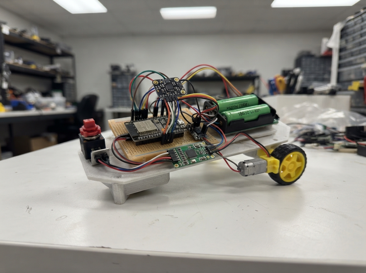
This project builds a self-balancing platform using an ESP32 microcontroller, dual N20 micro motors, and an MPU-6050 inertial measurement unit. The system continuously reads pitch angle from the IMU and applies corrective motor commands through a DRV8833 driver to maintain balance, with a safety-focused design that includes an emergency stop switch, battery protection board, and restrained test frame for safe development.
The guide provides a complete wiring diagram, parts list with battery and power management components, and step-by-step assembly instructions for building the mechanical frame and electrical connections. Firmware is included with a PID control loop running at 200 Hz, complementary filtering for angle estimation, and configurable tuning parameters—all designed for iterative bench testing before deployment.
Wiring diagram

Gather all the parts
Assemble it in 6 steps
1. Build and restrain the test frame
Make a rigid deck about 35 cm wide. Fix one geared motor and wheel at each end so both wheel axles are level and parallel. Clamp the deck in a test stand or hang it from a strong strap so the wheels can turn without carrying a person.
- Start with the wheels off the floor; this lets you confirm direction without the rig escaping.
- Do not stand on, ride, or hold this prototype between your feet. A software mistake can make the wheels spin suddenly.
2. Wire the motors to the driver
Connect the left motor’s two terminals to AOUT1 and AOUT2 on motor_driver_1, and connect the right motor’s two terminals to BOUT1 and BOUT2. If a wheel later corrects in the wrong direction, unplug the battery and swap that motor’s two wires.
- Use thicker, short wires for the motors because motor current is much larger than the sensor current.
- Never move motor wires while the battery is connected; a loose wire can short the battery or damage the driver.
3. Connect the battery protection and stop switch
Put two matched protected 18650 cells into battery_holder in the direction marked on its plastic case. Connect BAT+ to bms_2s B+ and BAT- to B-. Connect BMS P+ to estop_1 COM. Join BMS P- to the shared GND rail. Connect estop_1 NC to both buck-converter inputs; pressing the red button must remove power from both converters.
- Set buck_5v to exactly 5.0 V and motor_buck_6v to exactly 6.0 V with a multimeter before connecting either output to the board or driver.
- A 2-cell Li-ion pack can deliver enough current to melt thin wires. Fit the cells last, use an appropriate 2S BMS, and make sure no bare positive wire can touch ground.
- Do not charge the two cells through this project as drawn; use a proper matched-cell 2S Li-ion charger connected according to the BMS manufacturer’s instructions.
4. Power the controller, sensor, and motor driver
Connect buck_5v VOUT to the ESP32 VIN or 5V pin and connect its GND to ESP32 GND. Connect motor_buck_6v VOUT+ to motor_driver_1 VM and VOUT- to GND. Connect motor_driver_1 GND to the same GND rail. Connect imu_1 VIN to ESP32 3V3 and imu_1 GND to GND.
- Every part needs the same ground wire; without it, the control signals have no shared reference.
- Do not connect the 6.0 V motor supply to the ESP32, MPU-6050, or their 3.3 V pins; that can damage them.
5. Connect the small signal wires
Connect imu_1 SDA to ESP32 GPIO21 and imu_1 SCL to GPIO22. Connect motor_driver_1 AIN1 to GPIO25, AIN2 to GPIO26, BIN1 to GPIO27, BIN2 to GPIO32, and nSLEEP to GPIO33. Connect motor_driver_1 nFAULT to GPIO14. Connect fault_pullup between that same nFAULT wire and ESP32 3V3: resistor A joins nFAULT and resistor B goes to 3V3.
- Keep the MPU-6050 firmly fixed at the centre of the deck, with its printed axes aligned consistently with the deck; loose mounting makes the angle reading unreliable.
- Make sure VCC and GND are not swapped on the sensor — swapped power can damage it. Keep motor wires away from the sensor wires to reduce electrical noise.
6. Perform the first restrained test
Leave the wheels raised or the frame firmly clamped. Release the emergency-stop button, power the rig, and hold it upright and still for the short calibration period. Then gently tip it a few degrees while ready to press the stop button. If either wheel drives farther into the fall, press stop, remove the battery, and swap that motor’s two wires.
- The initial motor command is limited to reduce test risk. The code turns both motors off if the tilt passes about 35 degrees or the IMU/driver reports a fault.
- Keep hands, hair, and loose clothing away from the spinning wheels. Press the emergency stop immediately if the rig moves unexpectedly.
Review all connections
1. Connections between "battery_holder" and "ESP32"
2. Connections between "bms_2s" and "ESP32"
3. Connections between "estop_1" and "ESP32"
4. Connections between "buck_5v" and "ESP32"
5. Connections between "motor_buck_6v" and "ESP32"
6. Connections between "imu_1" and "ESP32"
7. Connections between "motor_driver_1" and "ESP32"
8. Connections between "fault_pullup" and "ESP32"
Deploy the firmware
#include <Arduino.h>
#include <Wire.h>
#include <math.h>


// Forward declarations
bool writeRegister(uint8_t reg, uint8_t value);
bool readMotion(int16_t &ax, int16_t &ay, int16_t &az, int16_t &gx, int16_t &gy, int16_t &gz);
void stopMotors();
void setOneMotor(int in1, int in2, int command);
void disableForFault(const char *reason);
bool calibrateImu();

constexpr uint8_t MPU_ADDR = 0x68;
constexpr int MOTOR_A_IN1 = 25;
constexpr int MOTOR_A_IN2 = 26;
constexpr int MOTOR_B_IN1 = 27;
constexpr int MOTOR_B_IN2 = 32;
constexpr int DRIVER_SLEEP_PIN = 33;
constexpr int DRIVER_FAULT_PIN = 14;
constexpr int IMU_SDA_PIN = 21;
constexpr int IMU_SCL_PIN = 22;

constexpr float LOOP_SECONDS = 0.005f;       // 200 Hz
constexpr float COMPLEMENTARY_ALPHA = 0.985f;
constexpr float TILT_CUTOFF_DEG = 35.0f;
constexpr int MAX_PWM = 130;                 // deliberately limited for bench testing
constexpr float KP = 8.0f;
constexpr float KI = 0.15f;
constexpr float KD = 0.22f;

float pitchDeg = 0.0f;
float gyroBiasY = 0.0f;
float integral = 0.0f;
float previousError = 0.0f;
bool armed = false;
unsigned long lastLoopUs = 0;

bool writeRegister(uint8_t reg, uint8_t value) {
  Wire.beginTransmission(MPU_ADDR);
  Wire.write(reg);
  Wire.write(value);
  return Wire.endTransmission() == 0;
}

bool readMotion(int16_t &ax, int16_t &ay, int16_t &az, int16_t &gx, int16_t &gy, int16_t &gz) {
  Wire.beginTransmission(MPU_ADDR);
  Wire.write(0x3B);
  if (Wire.endTransmission(false) != 0 || Wire.requestFrom(MPU_ADDR, (uint8_t)14) != 14) return false;
  ax = (Wire.read() << 8) | Wire.read();
  ay = (Wire.read() << 8) | Wire.read();
  az = (Wire.read() << 8) | Wire.read();
  gx = (Wire.read() << 8) | Wire.read();
  gy = (Wire.read() << 8) | Wire.read();
  gz = (Wire.read() << 8) | Wire.read();
  return true;
}

void stopMotors() {
  analogWrite(MOTOR_A_IN1, 0);
  analogWrite(MOTOR_A_IN2, 0);
  analogWrite(MOTOR_B_IN1, 0);
  analogWrite(MOTOR_B_IN2, 0);
}

void setOneMotor(int in1, int in2, int command) {
  command = constrain(command, -MAX_PWM, MAX_PWM);
  if (command > 0) {
    analogWrite(in1, command);
    analogWrite(in2, 0);
  } else if (command < 0) {
    analogWrite(in1, 0);
    analogWrite(in2, -command);
  } else {
    analogWrite(in1, 0);
    analogWrite(in2, 0);
  }
}

void disableForFault(const char *reason) {
  armed = false;
  integral = 0.0f;
  stopMotors();
  digitalWrite(DRIVER_SLEEP_PIN, LOW);
  Serial.println(reason);
}

bool calibrateImu() {
  const int samples = 600;
  float gyroTotal = 0.0f;
  float pitchTotal = 0.0f;
  for (int i = 0; i < samples; ++i) {
    int16_t ax, ay, az, gx, gy, gz;
    if (!readMotion(ax, ay, az, gx, gy, gz)) return false;
    gyroTotal += gy;
    pitchTotal += atan2f((float)ax, sqrtf((float)ay * ay + (float)az * az)) * 180.0f / PI;
    delay(3);
  }
  gyroBiasY = gyroTotal / samples;
  pitchDeg = pitchTotal / samples;
  return true;
}

void setup() {
  Serial.begin(115200);
  pinMode(MOTOR_A_IN1, OUTPUT);
  pinMode(MOTOR_A_IN2, OUTPUT);
  pinMode(MOTOR_B_IN1, OUTPUT);
  pinMode(MOTOR_B_IN2, OUTPUT);
  pinMode(DRIVER_SLEEP_PIN, OUTPUT);
  pinMode(DRIVER_FAULT_PIN, INPUT); // external 10 kOhm pull-up is fitted
  stopMotors();
  digitalWrite(DRIVER_SLEEP_PIN, LOW);

  Wire.begin(IMU_SDA_PIN, IMU_SCL_PIN);
  Wire.setClock(400000);
  if (!writeRegister(0x6B, 0x00) || !writeRegister(0x1B, 0x00) || !writeRegister(0x1C, 0x00)) {
    Serial.println("IMU not detected; motors remain off.");
    return;
  }

  Serial.println("Hold the secured rig upright and still: calibrating IMU.");
  if (!calibrateImu()) {
    Serial.println("IMU read failed; motors remain off.");
    return;
  }
  if (digitalRead(DRIVER_FAULT_PIN) == LOW) {
    Serial.println("Motor-driver fault present; motors remain off.");
    return;
  }
  digitalWrite(DRIVER_SLEEP_PIN, HIGH);
  armed = true;
  lastLoopUs = micros();
  Serial.println("Armed at low power. Keep the rig restrained.");
}

void loop() {
  if (!armed) {
    delay(50);
    return;
  }

  const unsigned long now = micros();
  if ((unsigned long)(now - lastLoopUs) < 5000) return;
  float dt = (now - lastLoopUs) / 1000000.0f;
  lastLoopUs = now;
  if (dt > 0.02f) dt = LOOP_SECONDS;

  if (digitalRead(DRIVER_FAULT_PIN) == LOW) {
    disableForFault("Motor-driver fault: motors disabled.");
    return;
  }

  int16_t ax, ay, az, gx, gy, gz;
  if (!readMotion(ax, ay, az, gx, gy, gz)) {
    disableForFault("IMU communication fault: motors disabled.");
    return;
  }

  const float accelPitch = atan2f((float)ax, sqrtf((float)ay * ay + (float)az * az)) * 180.0f / PI;
  const float gyroRate = ((float)gy - gyroBiasY) / 131.0f;
  pitchDeg = COMPLEMENTARY_ALPHA * (pitchDeg + gyroRate * dt) + (1.0f - COMPLEMENTARY_ALPHA) * accelPitch;

  if (fabsf(pitchDeg) > TILT_CUTOFF_DEG) {
    disableForFault("Tilt cutoff: stand the rig upright, then reset power.");
    return;
  }

  const float error = -pitchDeg; // upright is the calibrated zero-angle target
  integral = constrain(integral + error * dt, -20.0f, 20.0f);
  const float derivative = (error - previousError) / dt;
  previousError = error;
  const int motorCommand = (int)(KP * error + KI * integral + KD * derivative);

  // Same command on both wheels: balance only. No rider/joystick motion control in this bench prototype.
  setOneMotor(MOTOR_A_IN1, MOTOR_A_IN2, motorCommand);
  setOneMotor(MOTOR_B_IN1, MOTOR_B_IN2, motorCommand);
}
Remix this project
Make it yours in one click
Open a full copy of this project in your own Schematik workspace — diagram, code, parts, and assembly steps included. Swap the sensor, add features, or redesign the whole thing with AI. The author's original stays untouched.