Community project
Golf 3 LCD Dashboard Upgrade
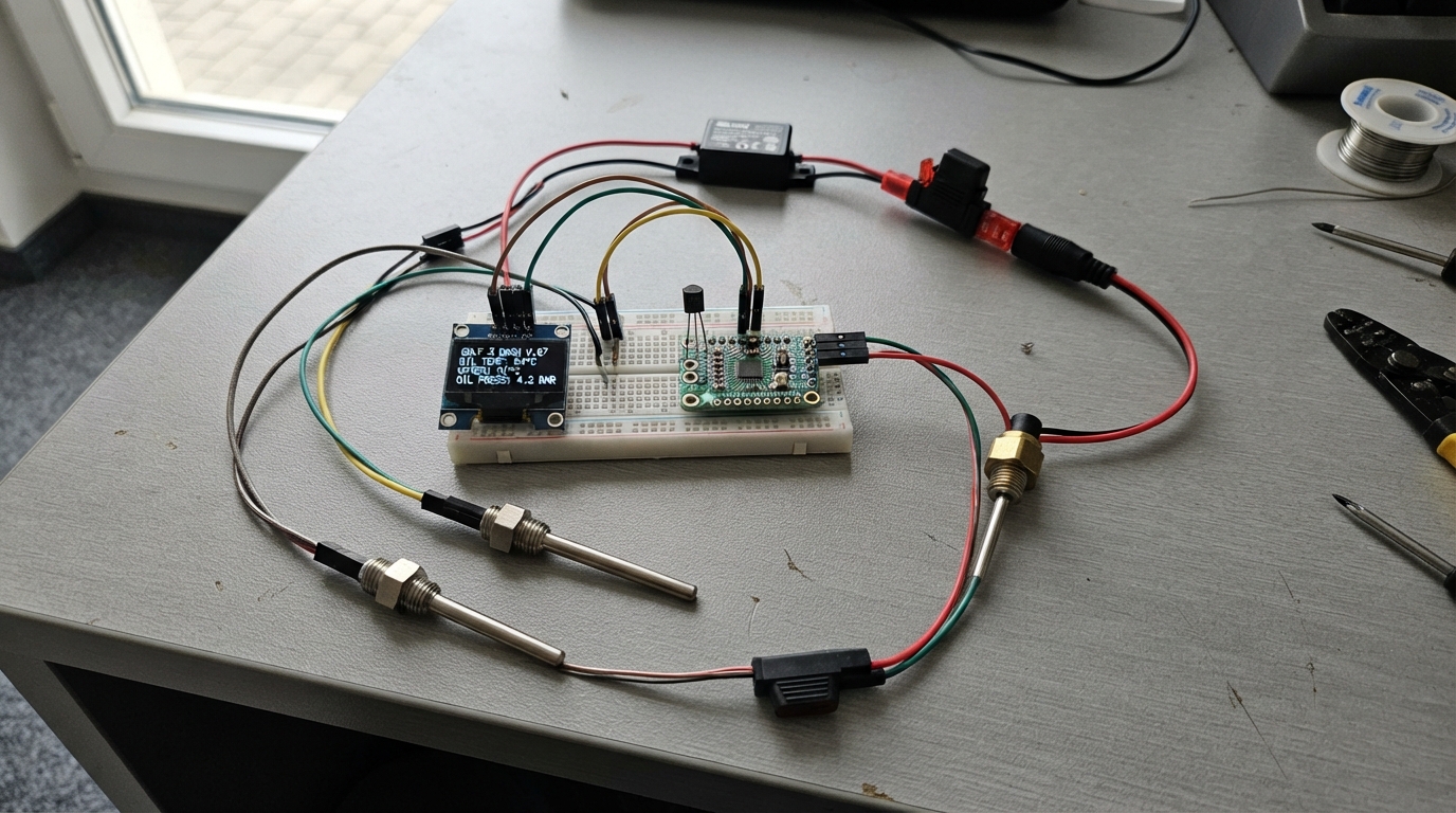
This guide upgrades a VW Golf 3 dashboard with a custom LCD display powered by an ESP32 microcontroller. The system reads real-time engine data including oil temperature, coolant temperature, outside air temperature, oil pressure, and vehicle voltage, displaying all metrics on a compact OLED screen.
Builders will receive a complete wiring diagram, full parts list with sensor specifications, step-by-step assembly instructions, and Arduino firmware ready to upload. The project integrates PT100 temperature probes via MAX31865 amplifiers, a pressure transducer, and a DS18B20 outside-air sensor, all powered safely through a regulated 12V-to-5V converter with inline fuse protection.
Wiring diagram

Gather all the parts
Assemble it in 7 steps
1. Prepare the display module on the bench
With the car switched off, place the ESP32, OLED and the two MAX31865 boards in a small non-metal enclosure behind the centre console. Connect the OLED: VCC → ESP32 3V3 (power), GND → ESP32 GND (ground), SDA → GPIO21 (data), SCL → GPIO22 (data).
- Test-fit the OLED behind the chosen console opening before cutting plastic.
- Leave the ESP32 USB socket reachable until the first successful flash.
- Do not let the circuit board or bare pins touch the metal dashboard frame — this can short the electronics.
2. Wire both temperature-interface boards
Wire both MAX31865 boards to the ESP32: each VIN → 3V3 (power), each GND → GND (ground), each SCK → GPIO18 (clock), each SDI → GPIO23 (data to board), and each SDO → GPIO19 (data from board). Connect the oil board CS → GPIO16 (select), and the coolant board CS → GPIO17 (select). For each two-wire PT100 probe, connect one probe lead to both F+ and RTD+ and the other probe lead to both F- and RTD- on its own MAX31865 board.
- Mark the oil probe cable and coolant probe cable before routing them through the bulkhead so they cannot be mixed up.
- Twist each long probe-wire pair together to reduce electrical noise.
- Do not splice either added temperature probe into the factory coolant-temperature-sensor wiring — that can make the engine controller or dashboard read incorrectly.
3. Add the outside-air sensor
Mount the DS18B20 where it sees outside air but not radiator heat, for example behind the front bumper away from the radiator. Wire VCC → 3V3 (power), GND → GND (ground), and DATA → GPIO4 (signal). Fit the 4.7 kΩ resistor between the same DATA/GPIO4 connection and 3V3; it keeps the sensor data wire at a readable level.
- Run this small sensor cable in protective sleeve and secure it away from the fan and belts.
- Do not mount the sensor beside the radiator or exhaust manifold — it will show an artificially high outside temperature after a stop.
4. Install the added oil sensors
Have the oil-pressure transducer and PT100 oil probe installed using a correctly threaded oil-filter sandwich plate or approved adapter. Keep the factory oil-pressure warning switch connected to the car exactly as it was. Wire the new pressure sensor +5V → protected 5 V (power), GND → the display-module GND (ground), and SIG → the 10 kΩ resistor. Connect the far end of that 10 kΩ resistor to the 20 kΩ resistor and to ESP32 GPIO32 (signal); connect the far end of the 20 kΩ resistor to GND.
- Use sensors and adapters rated for hot engine oil and verify the thread before fitting; the thread must never be forced.
- Route the added sensor cables well away from the exhaust manifold and moving belts.
- Do not remove or replace the factory oil-warning switch with this sensor — losing the factory warning can hide a dangerous loss of oil pressure.
- A leaking oil adapter can cause engine damage or fire; check for leaks with the engine running before refitting trim.
5. Install the coolant probe
Install the separate coolant PT100 probe in a correctly sized adapter or unused compatible coolant port. Do not disturb the factory coolant sensor. Refill and bleed the cooling system exactly as required for the engine, then check the adapter for leaks after the first heat cycle.
- Place the added probe where coolant flows, not in a trapped air pocket.
- Never open a hot cooling system — hot coolant can cause serious burns.
6. Add protected ignition power
Take power only from an ignition-switched 12 V source, not a permanent battery feed. Connect that source → the IN side of the 1 A inline fuse (power); fuse OUT → DC-DC VIN+ (protected power); DC-DC VIN- and VOUT- → a clean body ground (ground). Connect DC-DC VOUT+ → ESP32 5V/VIN and the pressure-sensor +5V (power). For voltage reading, connect fused 12 V → 100 kΩ resistor → 22 kΩ resistor → GND, and connect their joining point to GPIO33 (signal).
- Mount the fuse holder close to the point where the added wire joins the car.
- Use crimp terminals and heat-shrink tubing rather than twisting wires together.
- Never connect the ESP32, OLED, or any GPIO directly to the car's 12 V wire — the car voltage can damage them immediately.
- Disconnect the battery negative terminal before making connections; reconnect it only after inspecting for trapped or bare wires.
7. Check before closing the console
Before refitting trim, inspect every connection, make sure VCC and GND are not swapped, and make sure no wire can reach pedals, the steering shaft, the handbrake mechanism, hot exhaust parts, or sharp metal edges. Turn on the ignition and confirm the OLED shows voltage and sensor pages; the original dashboard oil warning must still perform its normal self-check.
- Use the displayed battery voltage as a rough check: with the engine stopped it is normally lower than with the engine running.
- If the factory oil warning behaves differently after the work, switch the engine off and correct the factory wiring before driving.
Review all connections
1. Connections between "fuse_1a" and "ESP32"
2. Connections between "buck_5v" and "ESP32"
3. Connections between "oled_1" and "ESP32"
4. Connections between "oil_rtd_interface" and "ESP32"
5. Connections between "coolant_rtd_interface" and "ESP32"
6. Connections between "outside_temp" and "ESP32"
7. Connections between "onewire_pullup" and "ESP32"
8. Connections between "oil_pressure_sensor" and "ESP32"
9. Connections between "pressure_divider_top" and "ESP32"
10. Connections between "pressure_divider_bottom" and "ESP32"
11. Connections between "voltage_divider_top" and "ESP32"
12. Connections between "voltage_divider_bottom" and "ESP32"
Deploy the firmware
#include <Wire.h>
#include <SPI.h>
#include <Adafruit_GFX.h>
#include <Adafruit_SH110X.h>
#include <Adafruit_MAX31865.h>
#include <OneWire.h>
#include <DallasTemperature.h>

#define OLED_SDA 21
#define OLED_SCL 22
#define SPI_SCK 18
#define SPI_MISO 19
#define SPI_MOSI 23
#define OIL_RTD_CS 16
#define COOLANT_RTD_CS 17
#define OUTSIDE_TEMP_PIN 4
#define PRESSURE_ADC_PIN 32
#define VEHICLE_VOLTAGE_ADC_PIN 33

constexpr float PRESSURE_DIVIDER_RATIO = 1.5f;
constexpr float VEHICLE_DIVIDER_RATIO = 122.0f / 22.0f;
constexpr float PRESSURE_SENSOR_MIN_V = 0.5f;
constexpr float PRESSURE_SENSOR_SPAN_V = 4.0f;
constexpr float PRESSURE_FULL_SCALE_BAR = 10.0f;

Adafruit_SH1106G display(128, 64, &Wire, -1);
Adafruit_MAX31865 oilRtd(OIL_RTD_CS);
Adafruit_MAX31865 coolantRtd(COOLANT_RTD_CS);
OneWire oneWire(OUTSIDE_TEMP_PIN);
DallasTemperature outsideSensor(&oneWire);

float oilC = NAN;
float coolantC = NAN;
float outsideC = NAN;
float oilBar = NAN;
float vehicleV = NAN;
uint8_t page = 0;
uint32_t lastSampleMs = 0;
uint32_t lastPageMs = 0;

float readAveragedVoltage(uint8_t pin) {
  uint32_t totalMv = 0;
  for (uint8_t i = 0; i < 16; ++i) {
    totalMv += analogReadMilliVolts(pin);
    delay(2);
  }
  return (totalMv / 16.0f) / 1000.0f;
}

float readRtdC(Adafruit_MAX31865 &rtd) {
  float resistance = rtd.readRTD() / 32768.0f * 430.0f;
  uint8_t fault = rtd.readFault();
  if (fault != 0 || resistance < 70.0f || resistance > 220.0f) {
    rtd.clearFault();
    return NAN;
  }
  return (resistance - 100.0f) / 0.385f;
}

void sampleSensors() {
  oilC = readRtdC(oilRtd);
  coolantC = readRtdC(coolantRtd);
  outsideSensor.requestTemperatures();
  float temp = outsideSensor.getTempCByIndex(0);
  outsideC = (temp == DEVICE_DISCONNECTED_C) ? NAN : temp;

  float sensorVoltage = readAveragedVoltage(PRESSURE_ADC_PIN) * PRESSURE_DIVIDER_RATIO;
  oilBar = (sensorVoltage - PRESSURE_SENSOR_MIN_V) * PRESSURE_FULL_SCALE_BAR / PRESSURE_SENSOR_SPAN_V;
  oilBar = constrain(oilBar, 0.0f, PRESSURE_FULL_SCALE_BAR);
  vehicleV = readAveragedVoltage(VEHICLE_VOLTAGE_ADC_PIN) * VEHICLE_DIVIDER_RATIO;
}

void printValue(float value, uint8_t decimals, const char *unit) {
  if (isnan(value)) display.print(F("---"));
  else display.print(value, decimals);
  display.print(unit);
}

void drawPage() {
  display.clearDisplay();
  display.setTextColor(SH110X_WHITE);
  display.setTextSize(1);
  if (page == 0) {
    display.setCursor(0, 0);
    display.print(F("GOLF 3 1.8 ABS"));
    display.setTextSize(2);
    display.setCursor(0, 17);
    printValue(vehicleV, 1, "V");
    display.setCursor(0, 42);
    printValue(oilBar, 1, "bar");
  } else if (page == 1) {
    display.setCursor(0, 0);
    display.print(F("TEMPERATURES"));
    display.setCursor(0, 18);
    display.print(F("OIL "));
    printValue(oilC, 0, "C");
    display.setCursor(0, 34);
    display.print(F("COOL "));
    printValue(coolantC, 0, "C");
    display.setCursor(0, 50);
    display.print(F("OUT "));
    printValue(outsideC, 0, "C");
  } else {
    display.setCursor(0, 0);
    display.print(F("OIL STATUS"));
    display.setTextSize(2);
    display.setCursor(0, 18);
    if (!isnan(oilBar) && oilBar < 0.6f) display.print(F("LOW!"));
    else display.print(F("OK"));
    display.setTextSize(1);
    display.setCursor(0, 50);
    display.print(F("Factory oil warning stays on"));
  }
  display.display();
}

void setup() {
  Wire.begin(OLED_SDA, OLED_SCL);
  SPI.begin(SPI_SCK, SPI_MISO, SPI_MOSI);
  analogReadResolution(12);
  analogSetPinAttenuation(PRESSURE_ADC_PIN, ADC_11db);
  analogSetPinAttenuation(VEHICLE_VOLTAGE_ADC_PIN, ADC_11db);
  display.begin(0x3C, true);
  display.clearDisplay();
  display.setTextColor(SH110X_WHITE);
  display.setTextSize(1);
  display.setCursor(0, 24);
  display.print(F("Golf 3 monitor"));
  display.display();
  oilRtd.begin(MAX31865_2WIRE);
  coolantRtd.begin(MAX31865_2WIRE);
  outsideSensor.begin();
  sampleSensors();
  drawPage();
}

void loop() {
  uint32_t now = millis();
  if (now - lastSampleMs >= 1000) {
    lastSampleMs = now;
    sampleSensors();
    drawPage();
  }
  if (now - lastPageMs >= 3000) {
    lastPageMs = now;
    page = (page + 1) % 3;
    drawPage();
  }
}
Remix this project
Make it yours in one click
Open a full copy of this project in your own Schematik workspace — diagram, code, parts, and assembly steps included. Swap the sensor, add features, or redesign the whole thing with AI. The author's original stays untouched.