Community project
Occupancy-Aware Room Lock
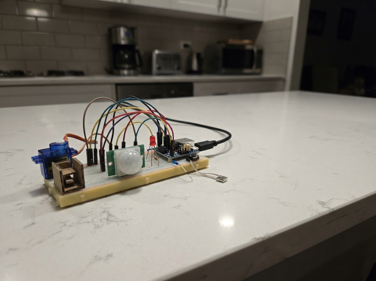
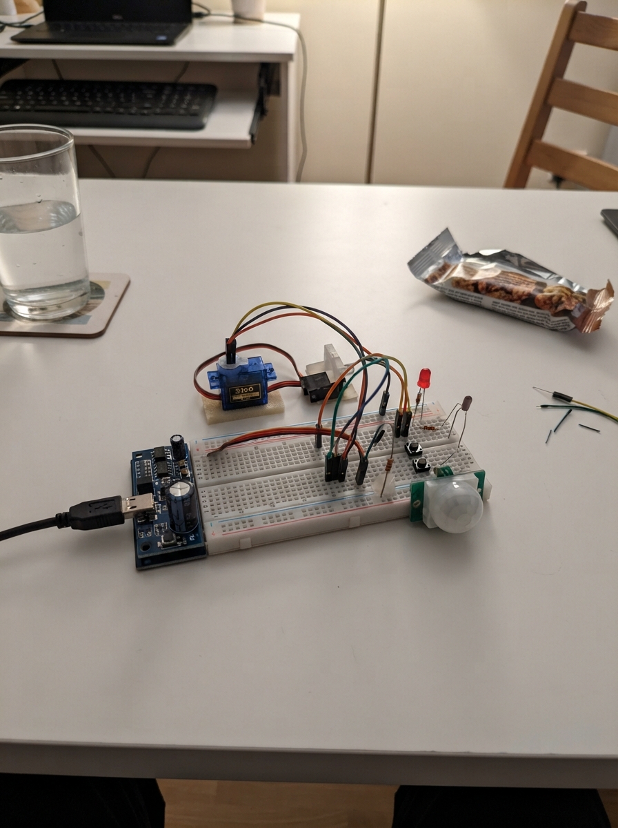
This occupancy-aware room lock uses an ESP32 microcontroller to automatically secure a door based on motion detection and manual controls. The system combines a servo-driven bolt mechanism with a PIR motion sensor to lock the room when unoccupied and unlock it when activity is detected, while allowing manual override via a release button and door reed switch.
Builders will receive a complete wiring diagram showing how to connect the SG90 servo, HC-SR501 PIR sensor, reed switch, release button, and status LEDs to the ESP32 breadboard setup. The guide includes a full parts list, step-by-step assembly instructions with power-supply configuration, and Arduino firmware that implements multiple operating modes (home, night, away, lock-away, alarm, smoke) with configurable motion timeouts and servo control logic.
Wiring diagram

Gather all the parts
Assemble it in 7 steps
1. Make a shared ground rail
Put the WeAct ESP32-C6-MiNi across the breadboard center gap. Run one black jumper from any C6 GND pin to the breadboard ground rail. Set the MB102 output selector used for this rail to 5 V, then run a second black jumper from MB102 GND to that same ground rail. This shared ground gives every signal the same reference.
- Power the WeAct board through its own USB-C port. The MB102 is a separate 5 V supply only for the servo and PIR.
- Do not connect the MB102 5 V rail to the C6 3V3 pin — 5 V can damage the 3.3 V board.
2. Add the servo power cushion
Put capacitor_470uf across the MB102 5 V and ground rails close to the servo connection. Connect its long positive lead, marked +, to 5 V and its striped negative lead to GND. This helps stop a servo twitch from making the board reset.
- Do not reverse the capacitor: putting its striped negative lead on 5 V can overheat or damage it.
3. Wire the lock servo
Connect servo_sg90 red to the MB102 5 V rail (power), brown or black to the shared GND rail (ground), and orange or yellow to C6 GPIO18 (signal). Mount the horn and bolt so 0 degrees is fully clear of the strike before trying 90 degrees as the locked position.
- The servo must use the MB102 5 V rail, never the C6 3V3 pin. Make sure its ground remains joined to the C6 ground or the signal will not be reliable.
4. Wire the room motion sensor
Connect pir_hcsr501 VCC to MB102 5 V (power), GND to the shared ground rail (ground), and OUT to C6 GPIO2 (signal). Move the small H/L jumper on the PIR to H so movement restarts its output time. Turn the delay knob low for this prototype, then wait through the 30-second warm-up after power is applied.
- The HC-SR501 output is normally about 3.3 V high even when its VCC is 5 V, so it can go directly to GPIO2; do not add a divider for this module.
- Do not use a PIR module with a 5 V logic output on GPIO2 — the ESP32-C6 input is not 5 V tolerant.
5. Fit the door and inside-release switches
Connect one reed_mc38 wire to GPIO10 and the other to GND (door-shut signal). Put the magnet on the moving door and the reed body on the frame, then check that the closed door brings them close together. Connect release_button NO to GPIO11 and COM to GND (inside-release signal). The code uses its built-in pull-up resistors, so no extra resistors are needed for either switch.
- When the door is shut, Serial state should show door as shut. Pressing the inside button should always request an immediate unlock.
- Keep the reed and magnet aligned; a large gap can make the lock think the door is open.
6. Add the two status lights
For the green unlocked light, connect GPIO6 to resistor_green P1, resistor_green P2 to led_green ANODE, and the LED short leg to GND. For the red locked light, connect GPIO7 to resistor_red P1, resistor_red P2 to led_red ANODE, and the LED short leg to GND. Each 330 ohm resistor limits the LED current.
- Do not omit either 330 ohm resistor — a direct GPIO-to-LED connection can damage the LED or overload the board pin.
7. Place and test the PIR coverage
Aim the PIR across the reading area, roughly chest height, rather than straight at the chair. Open Schematik’s serial output after deploying. Sit in the normal reading position, then make the tiny movements a reader normally makes: turn a page, shift posture, move a hand. Watch the printed seconds_since_last_motion number; it should reset to 0 during those movements. Stay still for the demo 30 seconds only if you want to confirm that the lock becomes eligible when the door is shut and the mode is away.
- A PIR detects changes in body heat, not a motionless person. It will often miss someone sitting perfectly still, so use its test result to decide whether the final product needs another occupancy method.
- Keep the prototype bolt where it cannot trap anyone. The inside button and smoke command are fail-open, but this breadboard prototype is not a certified door lock.
Review all connections
1. Connections between "mb102_5v" and "ESP32"
2. Connections between "capacitor_470uf" and "ESP32"
3. Connections between "servo_sg90" and "ESP32"
4. Connections between "pir_hcsr501" and "ESP32"
5. Connections between "reed_mc38" and "ESP32"
6. Connections between "release_button" and "ESP32"
7. Connections between "resistor_green" and "ESP32"
8. Connections between "led_green" and "ESP32"
9. Connections between "resistor_red" and "ESP32"
10. Connections between "led_red" and "ESP32"
Deploy the firmware
#include <Arduino.h>
#include <ESP32Servo.h>
#include "thread_stubs.h"

constexpr uint8_t SERVO_PIN = 18;
constexpr uint8_t PIR_PIN = 2;
constexpr uint8_t DOOR_REED_PIN = 10;
constexpr uint8_t RELEASE_BUTTON_PIN = 11;
constexpr uint8_t GREEN_LED_PIN = 6;
constexpr uint8_t RED_LED_PIN = 7;
constexpr uint8_t BUZZER_PIN = 3;  // Reserved only; connect an active buzzer later if wanted.

constexpr int UNLOCKED_ANGLE = 0;
constexpr int LOCKED_ANGLE = 90;
constexpr unsigned long PIR_WARMUP_MS = 30000UL;
constexpr unsigned long VACANCY_TIMEOUT_MS = 30000UL;  // Demo: use 600000UL for the final 10-minute timeout.
constexpr unsigned long SERVO_SETTLE_MS = 450UL;
constexpr unsigned long BUTTON_DEBOUNCE_MS = 35UL;
constexpr unsigned long STATUS_LOG_MS = 1000UL;

enum Mode { HOME, NIGHT, AWAY, LOCK_AWAY, ALARM, SMOKE };

Servo boltServo;
Mode currentMode = HOME;
bool locked = false;
bool roomOccupied = true;
bool previousPir = false;
bool previousButton = true;
bool servoSignalAttached = false;
unsigned long servoDetachAtMs = 0;
unsigned long bootMs = 0;
unsigned long lastMotionMs = 0;
unsigned long lastButtonEdgeMs = 0;
unsigned long lastStatusLogMs = 0;

const char *modeName(Mode mode) {
  switch (mode) {
    case HOME: return "home";
    case NIGHT: return "night";
    case AWAY: return "away";
    case LOCK_AWAY: return "lock-away";
    case ALARM: return "alarm";
    case SMOKE: return "smoke";
  }
  return "home";
}

bool doorShut() {
  // With INPUT_PULLUP, a closed reed wired to GND reads LOW.
  return digitalRead(DOOR_REED_PIN) == LOW;
}

bool modePermitsLock() {
  return currentMode == AWAY || currentMode == LOCK_AWAY || currentMode == ALARM;
}

void updateIndicators() {
  digitalWrite(GREEN_LED_PIN, locked ? LOW : HIGH);
  digitalWrite(RED_LED_PIN, locked ? HIGH : LOW);
}

void moveBolt(int angle) {
  // Attach only while moving; loop() detaches it after the settling time.
  boltServo.setPeriodHertz(50);
  boltServo.attach(SERVO_PIN, 500, 2400);
  boltServo.write(angle);
  servoSignalAttached = true;
  servoDetachAtMs = millis() + SERVO_SETTLE_MS;
}

void lockBolt() {
  if (locked) return;
  if (!doorShut()) {
    Serial.println("LOCK skipped: door is open");
    return;
  }
  moveBolt(LOCKED_ANGLE);
  locked = true;
  updateIndicators();
  sendEvent("locked");
  Serial.println("LOCKED");
}

void requestUnlock(const char *reason) {
  if (locked) {
    moveBolt(UNLOCKED_ANGLE);
    locked = false;
    updateIndicators();
    Serial.print("UNLOCKED: ");
    Serial.println(reason);
  }
}

void setModeFromText(const char *text) {
  if (strcmp(text, "home") == 0) currentMode = HOME;
  else if (strcmp(text, "night") == 0) currentMode = NIGHT;
  else if (strcmp(text, "away") == 0) currentMode = AWAY;
  else if (strcmp(text, "lock-away") == 0) currentMode = LOCK_AWAY;
  else if (strcmp(text, "alarm") == 0) currentMode = ALARM;
  else if (strcmp(text, "smoke") == 0) currentMode = SMOKE;
  else {
    Serial.println("ERR mode must be home, night, away, lock-away, alarm, or smoke");
    return;
  }

  Serial.print("MODE ");
  Serial.println(modeName(currentMode));
  if (currentMode == SMOKE) requestUnlock("smoke");
}

String currentStateJson() {
  String state = "{\"lock\":\"";
  state += locked ? "locked" : "unlocked";
  state += "\",\"door\":\"";
  state += doorShut() ? "shut" : "open";
  state += "\",\"room_occupied\":\"";
  state += roomOccupied ? "yes" : "no";
  state += "\",\"mode\":\"";
  state += modeName(currentMode);
  state += "\"}";
  return state;
}

void processSerial() {
  static String line;
  while (Serial.available()) {
    char c = static_cast<char>(Serial.read());
    if (c == '\n' || c == '\r') {
      line.trim();
      if (line.length()) onCommand(line.c_str());
      line = "";
    } else {
      line += c;
    }
  }
}

void setup() {
  Serial.begin(115200);
  pinMode(PIR_PIN, INPUT);
  pinMode(DOOR_REED_PIN, INPUT_PULLUP);
  pinMode(RELEASE_BUTTON_PIN, INPUT_PULLUP);
  pinMode(GREEN_LED_PIN, OUTPUT);
  pinMode(RED_LED_PIN, OUTPUT);
  pinMode(BUZZER_PIN, OUTPUT);
  digitalWrite(BUZZER_PIN, LOW);

  bootMs = millis();
  lastMotionMs = bootMs;
  previousPir = digitalRead(PIR_PIN) == HIGH;
  previousButton = digitalRead(RELEASE_BUTTON_PIN) == HIGH;
  updateIndicators();

  Serial.println("Nivasa Sentinel prototype started");
  Serial.println("PIR warm-up: 30 seconds. Serial commands: mode away | mode smoke | unlock | state");
}

void loop() {
  processSerial();
  const unsigned long now = millis();

  if (servoSignalAttached && static_cast<long>(now - servoDetachAtMs) >= 0) {
    boltServo.detach();
    servoSignalAttached = false;
  }

  // The inside release path is checked every pass through loop and is never delayed by lock decisions.
  const bool buttonHigh = digitalRead(RELEASE_BUTTON_PIN) == HIGH;
  if (previousButton && !buttonHigh && now - lastButtonEdgeMs >= BUTTON_DEBOUNCE_MS) {
    lastButtonEdgeMs = now;
    requestUnlock("manual_release");
    sendEvent("manual_release");
  }
  previousButton = buttonHigh;

  const bool pirHigh = digitalRead(PIR_PIN) == HIGH;
  if (now - bootMs >= PIR_WARMUP_MS && pirHigh && !previousPir) {
    lastMotionMs = now;
    roomOccupied = true;
    Serial.println("PIR motion");
    if (locked) {
      requestUnlock("person_inside");
      sendEvent("person_inside");
    }
  }
  previousPir = pirHigh;

  if (!doorShut() && locked) {
    requestUnlock("door_opened");
  }

  if (currentMode == SMOKE) {
    requestUnlock("smoke");
  }

  const unsigned long quietMs = now - lastMotionMs;
  if (!locked && modePermitsLock() && doorShut() && now - bootMs >= PIR_WARMUP_MS && quietMs >= VACANCY_TIMEOUT_MS) {
    roomOccupied = false;
    lockBolt();
  }

  if (now - lastStatusLogMs >= STATUS_LOG_MS) {
    lastStatusLogMs = now;
    Serial.print("seconds_since_last_motion=");
    Serial.print(quietMs / 1000UL);
    Serial.print(" ");
    Serial.println(currentStateJson());
  }
}
Remix this project
Make it yours in one click
Open a full copy of this project in your own Schematik workspace — diagram, code, parts, and assembly steps included. Swap the sensor, add features, or redesign the whole thing with AI. The author's original stays untouched.