Community project
Offline Home Security Hub
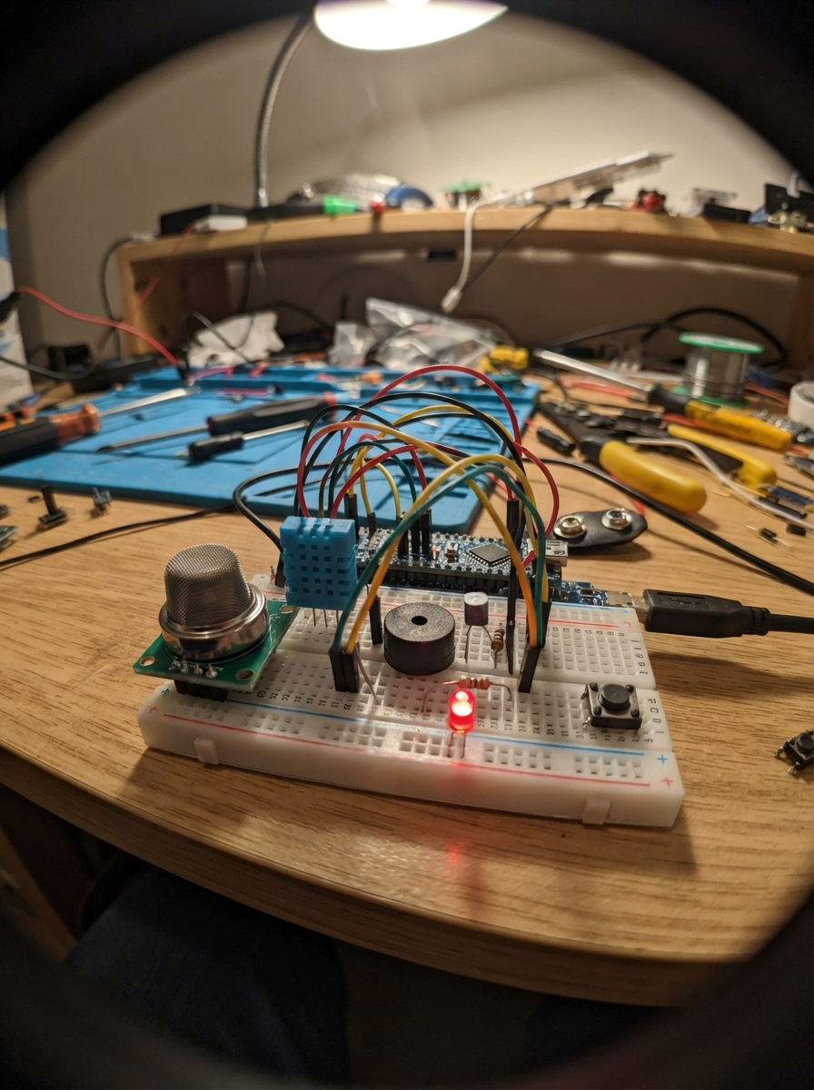
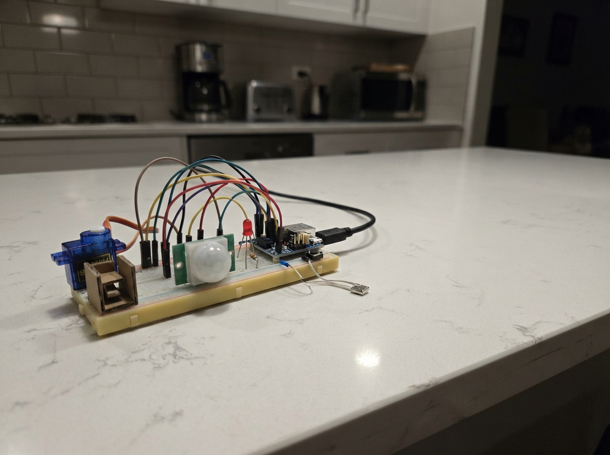
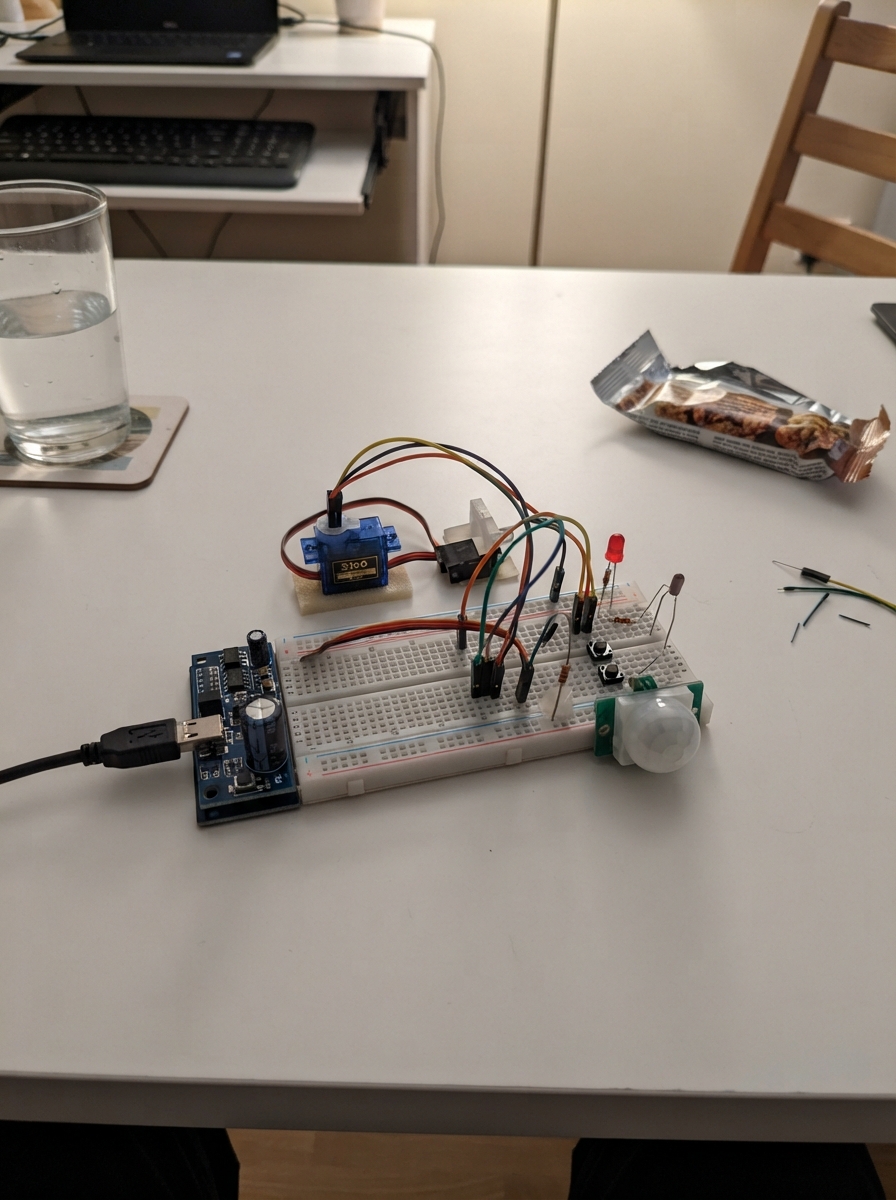
This offline home security hub runs on an ESP32-C6 microcontroller and provides local threat detection without relying on cloud connectivity. It monitors for smoke via an MQ-2 gas sensor, tracks environmental conditions with a DHT11 temperature sensor, and offers four security modes—Home, Away, Night, and Panic—each with visual feedback through status LEDs and audible alerts via a buzzer.
The guide includes a complete wiring diagram showing how to connect the mode selection buttons, status indicator lights, gas sensor input, and buzzer driver circuit using an NPN transistor. You'll also find the full firmware source code, a detailed parts list, and step-by-step assembly instructions for integrating both the main controller and optional WiFi expansion board via UART cross-connection.
Wiring diagram

Gather all the parts
Assemble it in 7 steps
1. Power both controller boards separately
Plug each WeAct ESP32-C6-MiNi into its own USB-C cable. Run one jumper from a GND pin on Core Thread to a GND pin on Core WiFi so both boards agree what a signal voltage means; do not join their 5 V pins because each board already receives USB power.
- Do not connect 5 V to any ESP32-C6 GPIO pin — these pins use 3.3 V only and 5 V can damage the board.
2. Wire the four mode keys
Place four momentary pushbuttons across the breadboard centre gap. For each button, connect one side to Core Thread GND and the opposite side to its GPIO: Home to GPIO10, Away to GPIO11, Night to GPIO2, and Panic to GPIO3. The code keeps each signal high until its button connects it to ground.
- GPIO14 from the original table is not broken out by the resolved WeAct-compatible pinout, so Night uses GPIO2 instead.
3. Wire the three mode lights
For each LED, connect its long leg through its own 330 Ω resistor to the controller: green to GPIO6, yellow to GPIO7, and red to GPIO19. Connect every short LED leg to GND. The resistors stop too much current damaging an LED or board pin.
- Make sure each LED has its own 330 Ω resistor; connecting an LED straight to a GPIO can damage it.
4. Build the buzzer switch
Check the BC547’s flat face and datasheet before inserting it because lead order can vary by maker. Connect GPIO18 through the 1 kΩ resistor to its base, emitter to GND, and collector to the buzzer negative pin. Connect buzzer positive to USB 5 V. Put the 1N4007 across the buzzer: striped cathode to 5 V and unstriped anode to the collector/buzzer-negative junction.
- Do not run the 5 V buzzer directly from GPIO18; the transistor is the safe switch.
- A reversed diode will not protect the circuit and can create a short when the buzzer runs.
5. Wire the MQ smoke input safely
Connect MQ-2 VCC to 5 V and GND to the shared ground. Connect MQ-2 AO to one end of the 12 kΩ resistor; join its other end to Core Thread GPIO0 and one end of the 20 kΩ resistor; connect the other 20 kΩ end to GND. Leave MQ-2 DO unconnected. This resistor pair reduces the sensor’s 5 V analogue output before it reaches the 3.3 V-only GPIO0.
- Never connect MQ-2 AO directly to GPIO0 because the MQ board can output close to 5 V and damage the ESP32-C6 input.
- The MQ heater becomes warm in normal use; keep it away from loose plastic and do not treat this prototype sensor as a certified fire detector.
6. Wire the optional temperature sensor
If using the DHT-11, connect VCC to 3V3, GND to GND, and DATA to GPIO1. Place the 10 kΩ resistor between DATA and 3V3. Do not power the DHT-11 from 5 V because its DATA wire would then rise to 5 V.
- Make sure the DHT-11’s VCC and GND are not swapped — swapped power can damage the sensor.
7. Cross-connect the two UART wires
Connect Core Thread GPIO22 to Core WiFi GPIO23, then Core Thread GPIO23 to Core WiFi GPIO22. Keep the GND-to-GND jumper from step 1 connected. These are 3.3 V signals, so no voltage converter is needed between the two ESP32-C6 boards.
- The lines must cross: transmit goes to receive, and receive goes to transmit.
Review all connections
1. Connections between "home_key_1" and "ESP32"
2. Connections between "away_key_1" and "ESP32"
3. Connections between "night_key_1" and "ESP32"
4. Connections between "panic_key_1" and "ESP32"
5. Connections between "green_led_resistor_1" and "ESP32"
6. Connections between "green_led_1" and "ESP32"
7. Connections between "yellow_led_resistor_1" and "ESP32"
8. Connections between "yellow_led_1" and "ESP32"
9. Connections between "red_led_resistor_1" and "ESP32"
10. Connections between "red_led_1" and "ESP32"
11. Connections between "buzzer_base_resistor_1" and "ESP32"
12. Connections between "bc547_1" and "ESP32"
13. Connections between "buzzer_5v_1" and "ESP32"
14. Connections between "flyback_diode_1" and "ESP32"
15. Connections between "mq2_1" and "ESP32"
16. Connections between "mq_divider_bottom_1" and "ESP32"
17. Connections between "dht11_1" and "ESP32"
18. Connections between "dht_pullup_1" and "ESP32"
19. Connections between "mq_divider_top_1" and "ESP32"
20. Connections between "core_wifi_1" and "ESP32"
Deploy the firmware
#include <Arduino.h>
#include "thread_mesh_stubs.h"

// Nivasa Core Thread: local security controller.
// UART1 uses GPIO22 TX -> Core WiFi GPIO23 RX and GPIO23 RX <- Core WiFi GPIO22 TX.
constexpr int HOME_KEY_PIN = 10;
constexpr int AWAY_KEY_PIN = 11;
constexpr int NIGHT_KEY_PIN = 2; // GPIO14 is not exposed by the resolved WeAct-compatible pinout.
constexpr int PANIC_KEY_PIN = 3;
constexpr int GREEN_LED_PIN = 6;
constexpr int YELLOW_LED_PIN = 7;
constexpr int RED_LED_PIN = 19;
constexpr int BUZZER_PIN = 18;
constexpr int MQ_PIN = 0;
constexpr int DHT_PIN = 1; // Reserved for optional DHT-11 hardware.
constexpr int LINK_TX_PIN = 22;
constexpr int LINK_RX_PIN = 23;

constexpr unsigned long PANIC_HOLD_MS = 2000;
constexpr unsigned long MQ_WARMUP_MS = 120000;
constexpr int SMOKE_THRESHOLD = 2200; // ADC raw value after the divider; tune only after observing a clean-air baseline.
constexpr unsigned long LOCK_IDLE_MS = 30000; // Demo value requested.
constexpr unsigned long LOCK_COUNTDOWN_MS = 120000;
constexpr unsigned long HEARTBEAT_MS = 5000;

enum Mode { HOME, AWAY, NIGHT, ALARM, SMOKE, LOCK_AWAY };
Mode mode = HOME;
String uartLine;
String states[8];
String stateNames[8];
uint8_t stateCount = 0;
String outPeople[8];
uint8_t outCount = 0;
bool mainDoorLocked = false;
bool locking = false;
unsigned long bootMs;
unsigned long panicPressedAt = 0;
unsigned long lockingStartedAt = 0;
unsigned long lastMovementAt = 0;
unsigned long lastHeartbeatAt = 0;
unsigned long lastSmokeSampleAt = 0;
unsigned long lastBuzzerChangeAt = 0;
bool buzzerOn = false;
uint8_t alarmStep = 0;

const char *modeText(Mode value) {
  switch (value) {
    case HOME: return "HOME";
    case AWAY: return "AWAY";
    case NIGHT: return "NIGHT";
    case ALARM: return "ALARM";
    case SMOKE: return "SMOKE";
    case LOCK_AWAY: return "LOCK_AWAY";
  }
  return "HOME";
}

void sendWiFi(const String &line) {
  Serial1.println(line);
  Serial.println("UART> " + line);
}

void setBuzzer(bool on) {
  buzzerOn = on;
  digitalWrite(BUZZER_PIN, on ? HIGH : LOW);
}

void updateLights() {
  digitalWrite(GREEN_LED_PIN, (mode == HOME) ? HIGH : LOW);
  digitalWrite(YELLOW_LED_PIN, (mode == AWAY || mode == NIGHT || mode == LOCK_AWAY) ? HIGH : LOW);
  digitalWrite(RED_LED_PIN, (mode == ALARM || mode == SMOKE) ? HIGH : LOW);
}

void setMode(Mode next, bool report = true) {
  if (mode == SMOKE && next != SMOKE) return; // Smoke remains dominant until power reset in this prototype.
  if (mode == next) return;
  mode = next;
  locking = false;
  updateLights();
  broadcastMode(modeText(mode));
  if (report) sendWiFi("MODE " + String(modeText(mode)));
}

void rememberState(const String &piece, const String &text) {
  for (uint8_t i = 0; i < stateCount; ++i) {
    if (stateNames[i] == piece) { states[i] = text; return; }
  }
  if (stateCount < 8) {
    stateNames[stateCount] = piece;
    states[stateCount] = text;
    ++stateCount;
  }
}

void raiseAlarm(const String &piece, const String &reason) {
  if (mode == SMOKE) return;
  onEvent(piece, reason);
  setMode(ALARM);
  sendWiFi("ALARM " + piece);
}

void enterSmoke() {
  if (mode == SMOKE) return;
  mode = SMOKE;
  locking = false;
  updateLights();
  broadcastMode("SMOKE");
  sendCmd("all", "UNLOCK");
  sendWiFi("SMOKE");
  sendWiFi("MODE SMOKE");
}

void startLockCountdown() {
  if (locking || mode == SMOKE || mode == ALARM) return;
  locking = true;
  lockingStartedAt = millis();
  sendWiFi("LOCKING 120");
}

void finishLockAway() {
  locking = false;
  sendCmd("all", "LOCK");
  setMode(LOCK_AWAY);
}

bool everyoneOut() {
  return outCount > 0; // Prototype has no configured family roster; each /out is treated as the known roster for demonstration.
}

void handleCommand(String line) {
  line.trim();
  if (line.length() == 0) return;
  Serial.println("CMD< " + line);

  if (line.startsWith("event ")) {
    int first = line.indexOf(' ', 6);
    if (first > 0) {
      String piece = line.substring(6, first);
      String name = line.substring(first + 1);
      if (name == "forced" || name == "tamper") raiseAlarm(piece, name);
      else if (name == "movement") lastMovementAt = millis();
    }
    return;
  }
  if (line == "smoke") { enterSmoke(); return; }
  if (line.startsWith("MODE ")) {
    String value = line.substring(5); value.toUpperCase();
    if (value == "HOME") setMode(HOME);
    else if (value == "AWAY") setMode(AWAY);
    else if (value == "NIGHT") setMode(NIGHT);
    return;
  }
  if (line.startsWith("UNLOCK ")) {
    String piece = line.substring(7);
    sendCmd(piece, "UNLOCK");
    return;
  }
  if (line.startsWith("OUT ")) {
    String person = line.substring(4);
    bool known = false;
    for (uint8_t i = 0; i < outCount; ++i) if (outPeople[i] == person) known = true;
    if (!known && outCount < 8) outPeople[outCount++] = person;
    if (everyoneOut() && mainDoorLocked && millis() - lastMovementAt >= LOCK_IDLE_MS) startLockCountdown();
    return;
  }
  if (line.startsWith("HOME ")) {
    String person = line.substring(5);
    for (uint8_t i = 0; i < outCount; ++i) {
      if (outPeople[i] == person) { outPeople[i] = outPeople[--outCount]; break; }
    }
    if (locking) { locking = false; sendWiFi("STATE core LOCK_CANCELLED"); }
    setMode(HOME);
    return;
  }
  if (line.startsWith("STATE ")) {
    int space = line.indexOf(' ', 6);
    if (space > 0) {
      String piece = line.substring(6, space);
      String text = line.substring(space + 1);
      rememberState(piece, text);
      if (piece == "door" && text == "LOCKED") mainDoorLocked = true;
      if (text == "MOVEMENT") lastMovementAt = millis();
      sendWiFi(line);
    }
  }
}

void serviceUart() {
  while (Serial1.available()) {
    char c = static_cast<char>(Serial1.read());
    if (c == '\n') { handleCommand(uartLine); uartLine = ""; }
    else if (c != '\r' && uartLine.length() < 120) uartLine += c;
  }
  while (Serial.available()) {
    char c = static_cast<char>(Serial.read());
    if (c == '\n') { handleCommand(uartLine); uartLine = ""; }
    else if (c != '\r' && uartLine.length() < 120) uartLine += c;
  }
}

void serviceKeys() {
  if (digitalRead(HOME_KEY_PIN) == LOW) { setMode(HOME); delay(25); }
  if (digitalRead(AWAY_KEY_PIN) == LOW) { setMode(AWAY); delay(25); }
  if (digitalRead(NIGHT_KEY_PIN) == LOW) { setMode(NIGHT); delay(25); }
  if (digitalRead(PANIC_KEY_PIN) == LOW) {
    if (panicPressedAt == 0) panicPressedAt = millis();
    if (millis() - panicPressedAt >= PANIC_HOLD_MS) { raiseAlarm("core", "panic"); panicPressedAt = ULONG_MAX / 2; }
  } else {
    panicPressedAt = 0;
  }
}

void serviceSmoke() {
  if (millis() - bootMs < MQ_WARMUP_MS || millis() - lastSmokeSampleAt < 500) return;
  lastSmokeSampleAt = millis();
  int raw = analogRead(MQ_PIN);
  Serial.printf("MQ raw: %d\n", raw);
  if (raw >= SMOKE_THRESHOLD) enterSmoke();
}

void serviceLocking() {
  if (!locking) return;
  unsigned long elapsed = millis() - lockingStartedAt;
  if (elapsed >= LOCK_COUNTDOWN_MS) finishLockAway();
}

void serviceBuzzer() {
  unsigned long now = millis();
  if (mode == SMOKE) { setBuzzer(true); return; } // Long continuous alarm.
  if (mode != ALARM) { setBuzzer(false); return; }
  static const unsigned long pattern[] = {180, 80, 420, 220}; // Active buzzer: alternating pulse lengths, not pitch.
  if (now - lastBuzzerChangeAt >= pattern[alarmStep]) {
    lastBuzzerChangeAt = now;
    alarmStep = (alarmStep + 1) % 4;
    setBuzzer(!buzzerOn);
  }
}

void setup() {
  Serial.begin(115200);
  Serial1.begin(115200, SERIAL_8N1, LINK_RX_PIN, LINK_TX_PIN);
  pinMode(HOME_KEY_PIN, INPUT_PULLUP); pinMode(AWAY_KEY_PIN, INPUT_PULLUP);
  pinMode(NIGHT_KEY_PIN, INPUT_PULLUP); pinMode(PANIC_KEY_PIN, INPUT_PULLUP);
  pinMode(GREEN_LED_PIN, OUTPUT); pinMode(YELLOW_LED_PIN, OUTPUT); pinMode(RED_LED_PIN, OUTPUT);
  pinMode(BUZZER_PIN, OUTPUT); setBuzzer(false);
  analogReadResolution(12);
  bootMs = millis(); lastMovementAt = bootMs;
  updateLights();
  Serial.println("Nivasa Core Thread ready. Test with: event pebble forced");
  sendWiFi("MODE HOME");
}

void loop() {
  serviceUart();
  serviceKeys();
  serviceSmoke();
  serviceLocking();
  serviceBuzzer();
  if (millis() - lastHeartbeatAt >= HEARTBEAT_MS) { lastHeartbeatAt = millis(); sendWiFi("HEARTBEAT"); }
}
Remix this project
Make it yours in one click
Open a full copy of this project in your own Schematik workspace — diagram, code, parts, and assembly steps included. Swap the sensor, add features, or redesign the whole thing with AI. The author's original stays untouched.