Community project
Https //www Unihiker Com Cn/wiki/k10
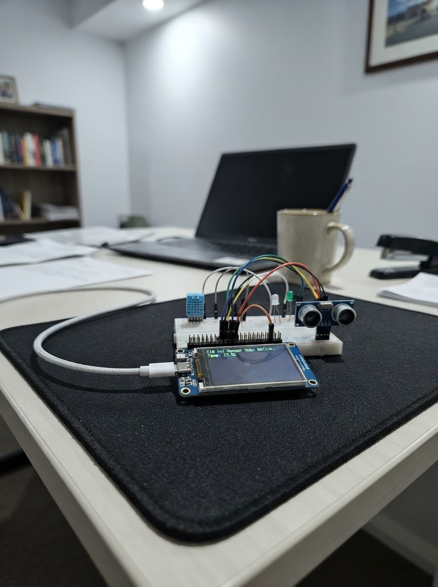
The UNIHIKER K10 is a compact ESP32-based development board with an integrated LCD display, perfect for learning embedded systems and building interactive projects. This starter guide walks through the essentials: powering up the board, uploading firmware, and displaying text on the screen.
Following this guide, makers will receive a complete parts list, wiring diagram, step-by-step assembly instructions, and ready-to-use Arduino firmware that displays uptime on the LCD. The project demonstrates core concepts like screen initialization, canvas drawing, and timed updates—a foundation for more complex applications.
Wiring diagram
Assemble it in 2 steps
1. Place the UNIHIKER K10 safely
Set the UNIHIKER K10 on a non-conductive surface with its screen facing upward. Leave the built-in sensors and screen unobstructed.
- Do not rest the board on loose metal objects or conductive foam.
- Avoid touching the board while it is powered if your hands are wet.
2. Connect USB-C power and programming cable
Connect a data-capable USB-C cable between the K10 and your computer. This project uses the board’s own USB power; no breadboard wiring or external components are required.
- Use a USB data cable, not a charge-only cable.
- Keep the cable connected while using Schematik’s Deploy button.
- Do not force the USB-C connector.
Deploy the firmware
#include <Arduino.h>
#include "unihiker_k10.h"


// Forward declarations
void drawScreen(uint32_t elapsedSeconds);

UNIHIKER_K10 k10;
const uint8_t SCREEN_DIRECTION = 2;
const uint32_t UPDATE_INTERVAL_MS = 1000;

uint32_t lastUpdateMs = 0;
uint32_t displayedSeconds = UINT32_MAX;

void drawScreen(uint32_t elapsedSeconds) {
  k10.canvas->canvasClear();
  k10.canvas->canvasText("UNIHIKER K10", 1, 0x0000FF);
  k10.canvas->canvasText("Starter project", 2, 0x0000FF);
  k10.canvas->canvasText("LCD is working!", 4, 0x00AA00);
  k10.canvas->canvasText("Uptime: " + String(elapsedSeconds) + " s", 6, 0x000000);
  k10.canvas->updateCanvas();
}

void setup() {
  Serial.begin(115200);
  k10.begin();
  k10.initScreen(SCREEN_DIRECTION);
  k10.creatCanvas();
  drawScreen(0);
  displayedSeconds = 0;
  lastUpdateMs = millis();
}

void loop() {
  const uint32_t now = millis();
  if (now - lastUpdateMs < UPDATE_INTERVAL_MS) {
    return;
  }

  lastUpdateMs = now;
  const uint32_t elapsedSeconds = now / 1000UL;
  if (elapsedSeconds != displayedSeconds) {
    drawScreen(elapsedSeconds);
    displayedSeconds = elapsedSeconds;
    Serial.println("K10 uptime: " + String(elapsedSeconds) + " seconds");
  }
}
Remix this project
Make it yours in one click
Open a full copy of this project in your own Schematik workspace — diagram, code, parts, and assembly steps included. Swap the sensor, add features, or redesign the whole thing with AI. The author's original stays untouched.