Community project
Indicator Timeout Buzzer
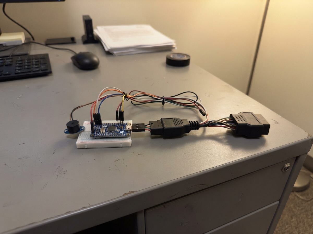
This project adds a smart reminder buzzer to motorcycles with CAN bus diagnostics. When the turn indicator blinks for more than 20 seconds without being cancelled, the ESP32 listens to the bike's CAN network, learns which message controls the indicator, and sounds a piezo buzzer to remind the rider. The guide includes a wiring diagram connecting the OBD-II adapter to the CAN transceiver and ESP32, a complete parts list, and firmware that automatically discovers the indicator signal during a learning phase.
Builders will get step-by-step assembly instructions that keep the motorcycle's original wiring intact, a learning routine that runs for one minute while the indicator blinks, and test procedures to verify the 20-second timeout reminder works correctly. The firmware uses the ESP32's CAN controller to monitor all bus traffic, scores candidate signals based on their blink pattern, and triggers the buzzer only after confirming the indicator has been left on too long.
Wiring diagram

Gather all the parts
Assemble it in 6 steps
1. Keep the motorcycle wiring untouched
Use a ready-made Triumph Euro-5 six-pin-to-16-pin OBD-II adapter lead and plug it into the red diagnostic socket under the seat, beside the fuse box. Plug the 16-pin OBD-II breakout pigtail into that lead; do not cut, probe, or splice the motorcycle harness.
- The breakout lead gives you three labelled wires to use: pin 6, pin 14, and pin 4 or 5.
- Do not connect the OBD-II pin 16 power wire to this project. Motorcycle supply voltage can damage the ESP32 and the CAN board.
2. Connect the CAN board to the ESP32
With the ESP32 unplugged, connect CAN Pal VCC to ESP32 3V3 (power), CAN Pal GND to ESP32 GND (ground), CAN Pal TX to GPIO22 (data), CAN Pal RX to GPIO21 (data), and CAN Pal SLNT to ESP32 3V3 (keeps the board silent so it cannot send messages to the motorcycle).
- Use short insulated jumper wires and check each printed label before applying USB power.
- Make sure VCC and GND are not swapped — swapped power can damage the CAN board. Do not connect the CAN Pal directly to 5 V.
3. Join the three diagnostic wires
Connect OBD breakout pin 6 / CAN-H to CAN Pal CANH (data), OBD breakout pin 14 / CAN-L to CAN Pal CANL (data), and OBD breakout pin 4 or 5 / GND to CAN Pal GND (ground). These are the only motorcycle connections used.
- Keep CAN-H and CAN-L together as a short pair where practical. The CAN Pal is a listener because its SLNT pin is tied to 3V3.
- Do not swap CAN-H and CAN-L; swapped wires prevent the ESP32 from reading the motorcycle network.
4. Wire the reminder sounder
Connect the piezo buzzer + terminal to ESP32 GPIO25 (sound signal) and its - terminal to ESP32 GND (ground).
- If the buzzer has no printed + and - marks, use a passive piezo buzzer rather than an amplified 5 V buzzer module.
- Do not use the motorcycle's 12 V supply for the buzzer — this small piezo is driven from the ESP32 only.
5. Teach it the indicator message
With the motorcycle safely parked and the engine off, hold the ESP32 BOOT button while plugging the ESP32 into USB. Release BOOT after it starts, then within one minute operate only the left or right turn signal. Leave it flashing until the ESP32 restarts; it saves the matching CAN pattern automatically.
- Keep other controls untouched while learning so the code can recognize the repeating turn-signal pattern.
- Do this while stationary. Do not test or adjust the device while riding.
6. Test the 20-second reminder
After learning, restart the ESP32 normally without holding BOOT. Turn on either direction indicator and leave it blinking. After 20 seconds the piezo gives a short chirp about once per second; cancel the indicator and the chirps stop within about two seconds.
- To learn again later, repeat the BOOT-button power-up step.
- Secure the finished board and wires in an insulated enclosure under the seat so they cannot touch hot, moving, or sharp motorcycle parts.
Review all connections
1. Connections between "can_transceiver" and "ESP32"
2. Connections between "piezo_buzzer" and "ESP32"
3. Connections between "obd_adapter" and "ESP32"
4. Connections between "obd_breakout" and "ESP32"
Deploy the firmware
#include <Arduino.h>
#include <Preferences.h>
#include "driver/twai.h"

// Verified against the current CAN Pal and piezo wiring.
constexpr int CAN_RX_PIN = 21;
constexpr int CAN_TX_PIN = 22;
constexpr int BUZZER_PIN = 25;
constexpr uint32_t CAN_BITRATE = 500000;
constexpr uint32_t LEARN_TIMEOUT_MS = 60000;
constexpr uint32_t BLINK_MIN_MS = 250;
constexpr uint32_t BLINK_MAX_MS = 1500;
constexpr uint32_t SIGNAL_GONE_MS = 2000;
constexpr uint32_t REMINDER_DELAY_MS = 20000;

struct LearnedSignal {
  uint32_t magic;
  uint32_t identifier;
  uint8_t byteIndex;
  uint8_t bitMask;
};

struct Candidate {
  bool used;
  uint32_t identifier;
  uint8_t byteIndex;
  uint8_t bitMask;
  bool lastState;
  uint32_t lastToggleMs;
  uint8_t score;
};

constexpr uint32_t SETTINGS_MAGIC = 0x5349474CUL;
constexpr size_t MAX_CANDIDATES = 48;
Preferences preferences;
LearnedSignal learned = {};
Candidate candidates[MAX_CANDIDATES] = {};
bool learningMode = false;
bool signalBitKnown = false;
bool lastLearnedBit = false;
uint32_t firstBlinkMs = 0;
uint32_t lastBlinkMs = 0;
uint32_t buzzerPhaseMs = 0;
bool buzzerOn = false;

void stopBuzzer() {
  ledcWriteTone(BUZZER_PIN, 0);
  buzzerOn = false;
}

void updateBuzzer(uint32_t now) {
  bool signalStillBlinking = firstBlinkMs != 0 && (now - lastBlinkMs) <= SIGNAL_GONE_MS;
  if (!signalStillBlinking) {
    firstBlinkMs = 0;
    stopBuzzer();
    return;
  }

  if ((now - firstBlinkMs) < REMINDER_DELAY_MS) {
    stopBuzzer();
    return;
  }

  // A short chirp once per second is noticeable without being a continuous distraction.
  uint32_t phase = now % 1000;
  bool shouldSound = phase < 180;
  if (shouldSound != buzzerOn) {
    ledcWriteTone(BUZZER_PIN, shouldSound ? 2600 : 0);
    buzzerOn = shouldSound;
  }
}

bool startCan() {
  twai_general_config_t general = TWAI_GENERAL_CONFIG_DEFAULT((gpio_num_t)CAN_TX_PIN, (gpio_num_t)CAN_RX_PIN, TWAI_MODE_LISTEN_ONLY);
  twai_timing_config_t timing = TWAI_TIMING_CONFIG_500KBITS();
  twai_filter_config_t filter = TWAI_FILTER_CONFIG_ACCEPT_ALL();
  if (twai_driver_install(&general, &timing, &filter) != ESP_OK) {
    return false;
  }
  return twai_start() == ESP_OK;
}

Candidate *findCandidate(uint32_t identifier, uint8_t byteIndex, uint8_t bitMask, bool state) {
  for (size_t i = 0; i < MAX_CANDIDATES; ++i) {
    if (candidates[i].used && candidates[i].identifier == identifier &&
        candidates[i].byteIndex == byteIndex && candidates[i].bitMask == bitMask) {
      return &candidates[i];
    }
  }
  for (size_t i = 0; i < MAX_CANDIDATES; ++i) {
    if (!candidates[i].used) {
      candidates[i] = {true, identifier, byteIndex, bitMask, state, 0, 0};
      return &candidates[i];
    }
  }
  return nullptr;
}

void saveLearned(Candidate &candidate) {
  learned.magic = SETTINGS_MAGIC;
  learned.identifier = candidate.identifier;
  learned.byteIndex = candidate.byteIndex;
  learned.bitMask = candidate.bitMask;
  preferences.putBytes("signal", &learned, sizeof(learned));
  learningMode = false;
  signalBitKnown = false;
  Serial.printf("Learned CAN ID 0x%lX, byte %u, mask 0x%02X. Restarting monitor.\n", (unsigned long)learned.identifier, learned.byteIndex, learned.bitMask);
  delay(300);
  ESP.restart();
}

void processLearningFrame(const twai_message_t &message, uint32_t now) {
  if (message.rtr || message.data_length_code == 0) return;
  for (uint8_t byteIndex = 0; byteIndex < message.data_length_code; ++byteIndex) {
    for (uint8_t bit = 0; bit < 8; ++bit) {
      uint8_t mask = (uint8_t)(1U << bit);
      bool state = (message.data[byteIndex] & mask) != 0;
      Candidate *candidate = findCandidate(message.identifier, byteIndex, mask, state);
      if (candidate == nullptr || state == candidate->lastState) continue;

      uint32_t interval = now - candidate->lastToggleMs;
      candidate->lastState = state;
      candidate->lastToggleMs = now;
      if (interval >= BLINK_MIN_MS && interval <= BLINK_MAX_MS) {
        candidate->score++;
      } else {
        candidate->score = 1;
      }
      if (candidate->score >= 6) {
        saveLearned(*candidate);
      }
    }
  }
}

void processMonitorFrame(const twai_message_t &message, uint32_t now) {
  if (message.rtr || message.identifier != learned.identifier || learned.byteIndex >= message.data_length_code) return;
  bool bit = (message.data[learned.byteIndex] & learned.bitMask) != 0;
  if (!signalBitKnown) {
    lastLearnedBit = bit;
    signalBitKnown = true;
    return;
  }
  if (bit != lastLearnedBit) {
    lastLearnedBit = bit;
    lastBlinkMs = now;
    if (firstBlinkMs == 0) {
      firstBlinkMs = now;
      Serial.println("Turn-signal blink detected; 20-second reminder timer started.");
    }
  }
}

void setup() {
  Serial.begin(115200);
  pinMode(BOOT_PIN, INPUT_PULLUP);
  pinMode(BUZZER_PIN, OUTPUT);
  ledcAttach(BUZZER_PIN, 2600, 8);
  stopBuzzer();

  preferences.begin("turnrem", false);
  size_t count = preferences.getBytesLength("signal");
  if (count == sizeof(learned)) preferences.getBytes("signal", &learned, sizeof(learned));

  // Hold the ESP32 BOOT button while powering it to replace the saved signal selection.
  learningMode = digitalRead(BOOT_PIN) == LOW || learned.magic != SETTINGS_MAGIC;
  if (learningMode) {
    memset(candidates, 0, sizeof(candidates));
    Serial.println("LEARNING: For the next 60 seconds, operate only one turn signal. Do not press other motorcycle controls.");
  } else {
    Serial.printf("Monitoring saved CAN ID 0x%lX. Hold BOOT during power-up to learn again.\n", (unsigned long)learned.identifier);
  }

  if (!startCan()) {
    Serial.println("CAN driver failed to start. Check CAN Pal wiring and use an ESP32 DevKit v1.");
  }
}

void loop() {
  twai_message_t message;
  uint32_t now = millis();
  while (twai_receive(&message, pdMS_TO_TICKS(5)) == ESP_OK) {
    if (learningMode) processLearningFrame(message, now);
    else processMonitorFrame(message, now);
    now = millis();
  }

  if (learningMode && now >= LEARN_TIMEOUT_MS) {
    Serial.println("No repeating indicator bit was learned. Restart while holding BOOT and try again with only a turn signal operating.");
    delay(1000);
    ESP.restart();
  }
  if (!learningMode) updateBuzzer(now);
  delay(1);
}
Remix this project
Make it yours in one click
Open a full copy of this project in your own Schematik workspace — diagram, code, parts, and assembly steps included. Swap the sensor, add features, or redesign the whole thing with AI. The author's original stays untouched.