Community project
Interactive Water Well
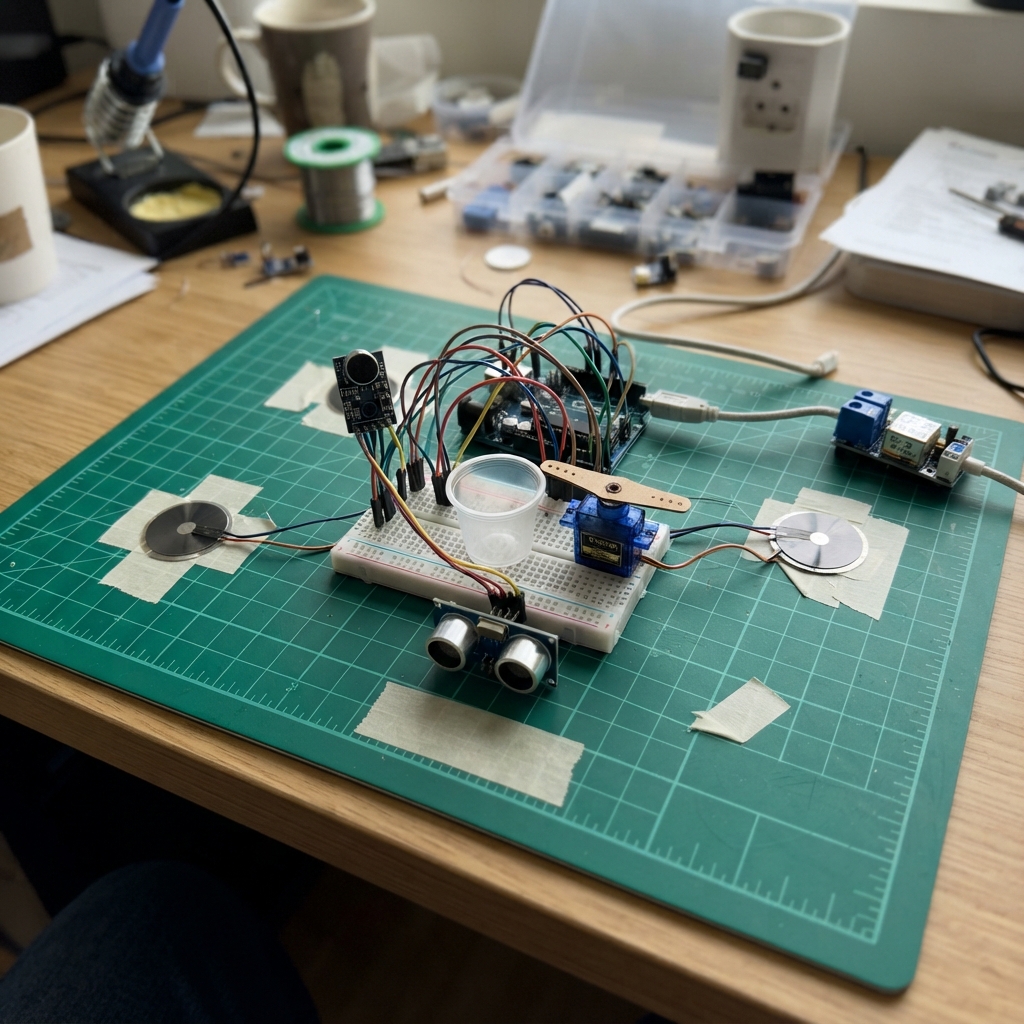
The Interactive Water Well is a touch-sensitive installation that responds to physical interaction across four zones. When visitors tap or touch the piezo sensors positioned around the well's perimeter, the system detects the impact location and intensity, triggering animated responses including servo-controlled boat movement and audio feedback through a sound sensor.
This guide provides a complete wiring diagram, parts list, and step-by-step assembly instructions for building the interactive system. The Arduino Uno firmware handles real-time sensor input from four piezo discs, a proximity sensor, and a microphone, allowing the well to create dynamic visual and physical responses. Builders will learn how to calibrate touch sensitivity, integrate servo control, and interface multiple analog sensors on a single microcontroller.
Wiring diagram

Gather all the parts
Assemble it in 7 steps
1. Prepara las tierras compartidas
Conecta GND del Arduino Uno a una línea de tierra de la protoboard. Conecta también allí el cable negro o marrón del SG90 y el negativo de la fuente externa de 5 V. Esta tierra común permite que la señal del Arduino controle el servo sin que el motor reinicie la placa.
- Deja el Arduino alimentado por USB del computador y usa la fuente externa solamente para el servo.
- No conectes el positivo de la fuente externa de 5 V al pin 5V del Arduino mientras el Uno está conectado por USB; una conexión incorrecta puede dañar el computador o la placa.
2. Monta y protege el piezo de la zona izquierda
Pega el disco piezo_left debajo de la zona izquierda de la superficie con cinta fuerte o adhesivo fino. Conecta un cable del disco a GND. Conecta su otro cable al extremo de entrada de r_series_left de 1 kΩ. En el otro extremo de esa resistencia crea un punto común: llévalo a A0, a un extremo de r_bleed_left de 1 MΩ y al lado sin franja de clamp_left. Conecta el otro extremo de la resistencia de 1 MΩ a GND y el lado con franja del diodo zener a GND.
- El resistor de 1 MΩ devuelve la señal a reposo después de cada toque; el diodo zener desvía picos fuertes antes de que lleguen al Arduino.
- No dobles ni sueldes directamente sobre la parte cerámica del disco; usa sus cables ya soldados.
- No conectes un piezo directamente a A0: un golpe puede producir picos de voltaje que dañen la entrada analógica.
3. Repite las otras tres zonas de toque
Monta piezo_top, piezo_right y piezo_bottom bajo las zonas superior, derecha e inferior. Para cada disco, un cable va a GND; el otro pasa por su resistor de 1 kΩ. El nodo después del resistor va respectivamente a A1, A2 o A3, a su resistor de 1 MΩ hacia GND y al lado sin franja de su zener; el lado con franja de cada zener va a GND.
- Haz una prueba tocando una zona cada vez: si dos zonas reaccionan siempre juntas, sepáralas físicamente con espuma, goma o divisiones mecánicas bajo la superficie.
- Mantén los cables de los piezos cortos y alejados del cable de alimentación del servo.
- Una superficie rígida transmite vibraciones entre zonas; el aislamiento mecánico es tan importante como el cableado para obtener posiciones distintas.
4. Conecta el sensor de sonido
Conecta VCC del mic a 5V del Arduino, GND a GND y AO a A4. No uses el pin DO para este proyecto: AO da una medida continua que permite distinguir voz, aplausos y silencio.
- Coloca el micrófono lejos del proyector, ventiladores y servo para que esos ruidos no creen olas falsas.
- El pequeño tornillo azul del KY-038 afecta sobre todo a la salida digital DO; el código usa AO, por lo que el filtrado principal se hace en software.
- No pongas el micrófono dentro de una caja completamente cerrada: el sonido llegaría amortiguado y la instalación reaccionaría poco.
5. Coloca el sensor de proximidad
Monta distance en un borde del círculo mirando hacia la zona desde la que se acerca el visitante, no mirando verticalmente al agua. Conecta VCC a 5V, GND a GND, TRIG a D7 y ECHO a D8.
- Inclina ligeramente el HC-SR04 hacia la persona para que no lea el borde opuesto ni el proyector.
- Una abertura limpia frente a los dos transductores redondos mejora las lecturas.
- Evita que el sensor apunte a una superficie de agua real muy inclinada o irregular; el eco puede desaparecer y aparecer de forma errática.
6. Alimenta y conecta el barquito
Fija el SG90 de modo que su brazo mueva un hilo, una varilla ligera o un mecanismo de giro del barquito, sin forzarlo contra los topes. Conecta el cable naranja o amarillo del servo a D9, el rojo al positivo de la fuente externa de 5 V y el marrón o negro a GND compartido. Conecta servo_capacitor en paralelo con el servo: su pata larga + al positivo externo de 5 V y su pata marcada con franja - a GND.
- Antes de acoplar el mecanismo al barco, enciende el sistema: el servo empieza centrado cerca de 90 grados.
- Deja holgura mecánica para que el barco no pueda tirar del brazo del servo al final de su recorrido.
- Respeta la franja negativa del capacitor: si se invierte puede calentarse o dañarse.
- El SG90 puede pedir picos de corriente mayores que el USB del Arduino; alimentarlo desde la fuente externa evita reinicios.
7. Conecta el Uno al computador y verifica los datos
Conecta el Arduino al computador por USB. El programa envía una línea de datos cada 40 ms: P1 a P4 indican la intensidad de cada zona, SOUND el sonido, DIST la distancia en centímetros y SERVO el ángulo que está ordenando al motor.
- En TouchDesigner usa un Serial DAT a 115200 baudios, separa cada línea por comas y luego cada dato por dos puntos.
- Trata DIST:-1 como 'sin persona detectada' y no como una distancia real.
Review all connections
1. Connections between "piezo_left" and "Arduino"
2. Connections between "piezo_top" and "Arduino"
3. Connections between "piezo_right" and "Arduino"
4. Connections between "piezo_bottom" and "Arduino"
5. Connections between "r_series_left" and "Arduino"
6. Connections between "r_series_top" and "Arduino"
7. Connections between "r_series_right" and "Arduino"
8. Connections between "r_series_bottom" and "Arduino"
9. Connections between "r_bleed_left" and "Arduino"
10. Connections between "r_bleed_top" and "Arduino"
11. Connections between "r_bleed_right" and "Arduino"
12. Connections between "r_bleed_bottom" and "Arduino"
13. Connections between "clamp_left" and "Arduino"
14. Connections between "clamp_top" and "Arduino"
15. Connections between "clamp_right" and "Arduino"
16. Connections between "clamp_bottom" and "Arduino"
17. Connections between "mic" and "Arduino"
18. Connections between "distance" and "Arduino"
19. Connections between "servo_supply" and "Arduino"
20. Connections between "servo" and "Arduino"
21. Connections between "servo_capacitor" and "Arduino"
Deploy the firmware
#include <Arduino.h>
#include <Servo.h>

// Arduino Uno pins. A0..A4 are written as their Arduino pin numbers.

// Forward declarations
int readPiezoPeak(uint8_t pin);
void updatePiezos();
void updateSound();
int readDistanceCm();
void updateBoat();
void sendToTouchDesigner();

const uint8_t PIEZO_LEFT_PIN   = A0;
const uint8_t PIEZO_TOP_PIN    = A1;
const uint8_t PIEZO_RIGHT_PIN  = A2;
const uint8_t PIEZO_BOTTOM_PIN = A3;
const uint8_t MIC_PIN          = A4;
const uint8_t TRIG_PIN = 7;
const uint8_t ECHO_PIN = 8;
const uint8_t SERVO_PIN = 9;

const uint8_t piezoPins[4] = {
  PIEZO_LEFT_PIN, PIEZO_TOP_PIN, PIEZO_RIGHT_PIN, PIEZO_BOTTOM_PIN
};

// Tune these during installation. Increase PIEZO_THRESHOLD if footsteps or
// projector vibration cause false ripples; decrease it if gentle taps are missed.
const int PIEZO_THRESHOLD = 28;
const int PIEZO_FULL_SCALE = 700;
const unsigned long PIEZO_HOLD_MS = 120;
const unsigned long PIEZO_COOLDOWN_MS = 70;

const int SOUND_NOISE_GATE = 14;  // peak-to-peak ADC counts ignored as room noise
const int SOUND_FULL_SCALE = 180;

Servo boatServo;
int piezoIntensity[4] = {0, 0, 0, 0};
unsigned long piezoUntil[4] = {0, 0, 0, 0};
unsigned long piezoLastHit[4] = {0, 0, 0, 0};
int soundIntensity = 0;
int distanceCm = -1;
int boatAngle = 90;

unsigned long lastDistanceMs = 0;
unsigned long lastSerialMs = 0;
unsigned long lastServoMs = 0;

int readPiezoPeak(uint8_t pin) {
  // A short burst captures a piezo's brief positive pulse.
  int peak = 0;
  for (uint8_t i = 0; i < 5; i++) {
    int value = analogRead(pin);
    if (value > peak) peak = value;
  }
  return peak;
}

void updatePiezos() {
  unsigned long now = millis();
  for (uint8_t i = 0; i < 4; i++) {
    int peak = readPiezoPeak(piezoPins[i]);
    if (peak >= PIEZO_THRESHOLD && now - piezoLastHit[i] >= PIEZO_COOLDOWN_MS) {
      piezoIntensity[i] = constrain(map(peak, PIEZO_THRESHOLD, PIEZO_FULL_SCALE, 1, 1000), 1, 1000);
      piezoUntil[i] = now + PIEZO_HOLD_MS;
      piezoLastHit[i] = now;
    }
    if (now >= piezoUntil[i]) piezoIntensity[i] = 0;
  }
}

void updateSound() {
  // The KY-038 signal sits around a changing midpoint. Peak-to-peak sampling
  // measures sound movement instead of treating that midpoint as sound.
  int minimum = 1023;
  int maximum = 0;
  for (uint8_t i = 0; i < 48; i++) {
    int sample = analogRead(MIC_PIN);
    if (sample < minimum) minimum = sample;
    if (sample > maximum) maximum = sample;
  }
  int peakToPeak = maximum - minimum;
  int rawSound = 0;
  if (peakToPeak > SOUND_NOISE_GATE) {
    rawSound = constrain(map(peakToPeak, SOUND_NOISE_GATE, SOUND_FULL_SCALE, 1, 1000), 1, 1000);
  }
  // Gentle smoothing stops visual flutter but preserves claps and speech changes.
  soundIntensity = (soundIntensity * 3 + rawSound) / 4;
  if (soundIntensity < 3) soundIntensity = 0;
}

int readDistanceCm() {
  digitalWrite(TRIG_PIN, LOW);
  delayMicroseconds(2);
  digitalWrite(TRIG_PIN, HIGH);
  delayMicroseconds(10);
  digitalWrite(TRIG_PIN, LOW);

  unsigned long duration = pulseIn(ECHO_PIN, HIGH, 20000UL);
  if (duration == 0) return -1;  // no usable echo
  int cm = (int)(duration / 58UL);
  if (cm < 2 || cm > 300) return -1;
  return cm;
}

void updateBoat() {
  unsigned long now = millis();
  if (now - lastServoMs < 50) return;  // about 20 position changes per second
  lastServoMs = now;

  // A slow base drift suggests calm water; sound adds a modest extra sway.
  float phase = (now % 6000UL) / 6000.0f * 6.2831853f;
  int sway = (int)(sin(phase) * 8.0f);
  int soundSway = map(soundIntensity, 0, 1000, 0, 16);
  int direction = ((now / 700UL) % 2 == 0) ? 1 : -1;
  boatAngle = constrain(90 + sway + direction * soundSway, 65, 115);
  boatServo.write(boatAngle);
}

void sendToTouchDesigner() {
  // Fixed, comma-separated key:value line. Zero means no current piezo event.
  Serial.print("P1:"); Serial.print(piezoIntensity[0]);
  Serial.print(",P2:"); Serial.print(piezoIntensity[1]);
  Serial.print(",P3:"); Serial.print(piezoIntensity[2]);
  Serial.print(",P4:"); Serial.print(piezoIntensity[3]);
  Serial.print(",SOUND:"); Serial.print(soundIntensity);
  Serial.print(",DIST:"); Serial.print(distanceCm);
  Serial.print(",SERVO:"); Serial.println(boatAngle);
}

void setup() {
  Serial.begin(115200);
  pinMode(TRIG_PIN, OUTPUT);
  pinMode(ECHO_PIN, INPUT);
  digitalWrite(TRIG_PIN, LOW);

  boatServo.attach(SERVO_PIN);
  boatServo.write(90);
}

void loop() {
  updatePiezos();
  updateSound();

  unsigned long now = millis();
  if (now - lastDistanceMs >= 80) {
    lastDistanceMs = now;
    distanceCm = readDistanceCm();
  }

  updateBoat();

  if (now - lastSerialMs >= 40) {
    lastSerialMs = now;
    sendToTouchDesigner();
  }
}
Remix this project
Make it yours in one click
Open a full copy of this project in your own Schematik workspace — diagram, code, parts, and assembly steps included. Swap the sensor, add features, or redesign the whole thing with AI. The author's original stays untouched.