Community project
Programmable Encoder Divider
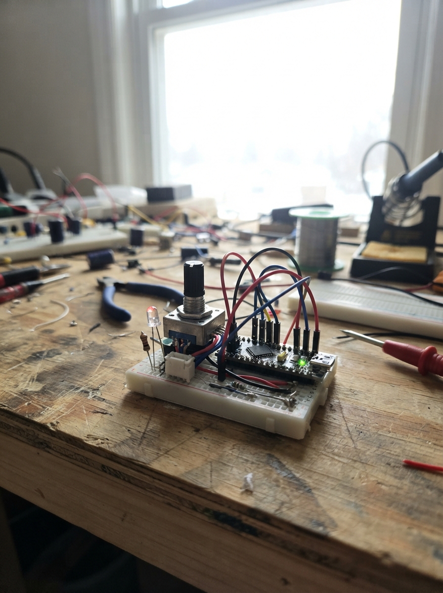
This project transforms an incremental optical encoder into a programmable divider that outputs quadrature signals at a fraction of the input rate. By configuring a divider value via serial commands, the Arduino processes encoder transitions and generates divided output pulses—useful for scaling motion control, testing, or interfacing encoders with systems requiring different resolution.
The guide provides a complete wiring diagram, parts list, and Arduino firmware with quadrature decoding logic. Assembly involves connecting the optical encoder to the Arduino's interrupt pins, wiring the divided-signal outputs, adding an indicator LED, and then configuring the divider ratio through the serial interface to match your application's needs.
Wiring diagram

Gather all the parts
Assemble it in 5 steps
1. Keep the board unpowered while wiring
Place the Arduino Uno, the optical encoder, the 4-way output connector, the green LED, and its 220 Ω resistor where their labels are easy to read. Leave the Uno USB cable unplugged while you attach wires.
- Use short wires for the encoder A and B signals if the encoder is close to the Uno.
- Do not connect or remove wires with the encoder or Uno powered; a loose wire can briefly touch the wrong pin.
2. Connect the optical encoder
Connect encoder VCC to the Uno 5V pin (power). Connect encoder GND to a Uno GND pin (ground). Connect encoder A to Uno D2 (signal), and encoder B to Uno D3 (signal).
- Look for A and B on the encoder label; some encoders call them channel A and channel B.
- Make sure VCC and GND are not swapped — swapped power can damage the encoder. This build expects 5 V digital A/B outputs; do not connect a higher-voltage encoder output directly to D2 or D3.
3. Wire the divided-signal output
Connect the output connector GND to a Uno GND pin (ground). Connect A_OUT to Uno D8 (signal) and B_OUT to Uno D9 (signal). Connect the optional +5V connector pin to the Uno 5V pin (power) only if the receiving device needs this reference supply.
- The receiver must share the Uno GND wire or it cannot reliably understand A_OUT and B_OUT.
- Do not connect the output connector +5V pin to another powered 5 V supply; two power supplies tied together can damage equipment.
4. Add the A_OUT indicator LED
Connect the A_OUT connector pin to one leg of the 220 Ω resistor (signal). Connect the resistor’s other leg to the LED’s long leg, called the anode (signal). Connect the LED’s short leg and flat-sided end, called the cathode, to Uno GND (ground). This LED is on the same A_OUT line as D8, so it flashes whenever the divided A output is high.
- The LED also makes A_OUT visible in the simulator.
- The resistor may go on either side of the LED, but it must remain in series with it.
- Do not connect the LED directly between D8/A_OUT and GND — without the 220 Ω resistor, excessive current can damage the LED or Arduino pin.
5. Power and set the divider
Check each connection once more, then plug the Uno into USB. After pressing Deploy, open its serial console at 115200 baud and send SET followed by the desired whole-number divider, such as SET 10. Send GET to see the current setting.
- The default is 10: the output changes one quadrature step after every ten valid incoming A/B changes.
- Use SET 1 when you want the output to follow every valid input change without division.
- This divider is intended for moderate-speed encoders. At very high shaft speeds, an Arduino Uno may miss edges; use faster dedicated hardware if every pulse at high speed is critical.
Review all connections
1. Connections between "optical_encoder_1" and "Arduino"
2. Connections between "output_receiver_1" and "Arduino"
3. Connections between "a_out_led_resistor_1" and "Arduino"
4. Connections between "a_out_indicator_1" and "Arduino"
Deploy the firmware
#include <Arduino.h>

void encoderChanged();
void writeOutputState(uint8_t state);
void printHelp();
void handleSerialCommand();

const uint8_t ENCODER_A_PIN = 2;
const uint8_t ENCODER_B_PIN = 3;
const uint8_t OUTPUT_A_PIN = 8;  // Also drives the A_OUT simulator/bench LED.
const uint8_t OUTPUT_B_PIN = 9;

volatile uint8_t previousState = 0;
volatile uint8_t outputState = 0;
volatile uint16_t divider = 10;
volatile uint16_t transitionCount = 0;
volatile bool outputChanged = false;

const int8_t QUADRATURE_DELTA[16] = {
  0, -1,  1,  0,
  1,  0,  0, -1,
 -1,  0,  0,  1,
  0,  1, -1,  0
};

void encoderChanged() {
  uint8_t currentState = (digitalRead(ENCODER_A_PIN) << 1) | digitalRead(ENCODER_B_PIN);
  int8_t delta = QUADRATURE_DELTA[(previousState << 2) | currentState];
  previousState = currentState;

  if (delta == 0) return;

  transitionCount++;
  if (transitionCount < divider) return;
  transitionCount = 0;

  if (delta > 0) {
    outputState = (outputState + 1) & 0x03;
  } else {
    outputState = (outputState + 3) & 0x03;
  }
  outputChanged = true;
}

void writeOutputState(uint8_t state) {
  digitalWrite(OUTPUT_A_PIN, (state >> 1) & 0x01);
  digitalWrite(OUTPUT_B_PIN, state & 0x01);
}

void printHelp() {
  Serial.println(F("Commands: SET n (1 to 65535), GET, HELP"));
  Serial.println(F("SET n: one output quadrature transition for every n valid input transitions."));
}

void handleSerialCommand() {
  static char command[24];
  static uint8_t length = 0;

  while (Serial.available()) {
    char c = (char)Serial.read();
    if (c == '\r') continue;
    if (c == '\n') {
      command[length] = '\0';
      length = 0;
      if (strncmp(command, "SET ", 4) == 0) {
        long requested = atol(command + 4);
        if (requested >= 1 && requested <= 65535) {
          noInterrupts();
          divider = (uint16_t)requested;
          transitionCount = 0;
          interrupts();
          Serial.print(F("Divider set to "));
          Serial.println(requested);
        } else {
          Serial.println(F("Use SET followed by a number from 1 to 65535."));
        }
      } else if (strcmp(command, "GET") == 0) {
        noInterrupts();
        uint16_t currentDivider = divider;
        interrupts();
        Serial.print(F("Divider is "));
        Serial.println(currentDivider);
      } else if (strcmp(command, "HELP") == 0 || command[0] == '\0') {
        printHelp();
      } else {
        Serial.println(F("Unknown command."));
        printHelp();
      }
    } else if (length < sizeof(command) - 1) {
      command[length++] = c;
    }
  }
}

void setup() {
  pinMode(ENCODER_A_PIN, INPUT_PULLUP);
  pinMode(ENCODER_B_PIN, INPUT_PULLUP);
  pinMode(OUTPUT_A_PIN, OUTPUT);
  pinMode(OUTPUT_B_PIN, OUTPUT);

  previousState = (digitalRead(ENCODER_A_PIN) << 1) | digitalRead(ENCODER_B_PIN);
  writeOutputState(outputState);

  Serial.begin(115200);
  Serial.println(F("Quadrature optical-encoder divider ready."));
  printHelp();

  attachInterrupt(digitalPinToInterrupt(ENCODER_A_PIN), encoderChanged, CHANGE);
  attachInterrupt(digitalPinToInterrupt(ENCODER_B_PIN), encoderChanged, CHANGE);
}

void loop() {
  if (outputChanged) {
    noInterrupts();
    uint8_t stateToWrite = outputState;
    outputChanged = false;
    interrupts();
    writeOutputState(stateToWrite);
  }
  handleSerialCommand();
}
Remix this project
Make it yours in one click
Open a full copy of this project in your own Schematik workspace — diagram, code, parts, and assembly steps included. Swap the sensor, add features, or redesign the whole thing with AI. The author's original stays untouched.
Related projects
MPU 6050 Logger and Tester
Arduino · September 28, 2026prahaladh.pradeep
Reloj Digital Con Temporizador
Arduino · September 27, 2026Ricardo Sprovieri
I M Building Test-phase Prototype Of Capstone Co
Arduino · September 27, 2026Fritz Blue Gadaza