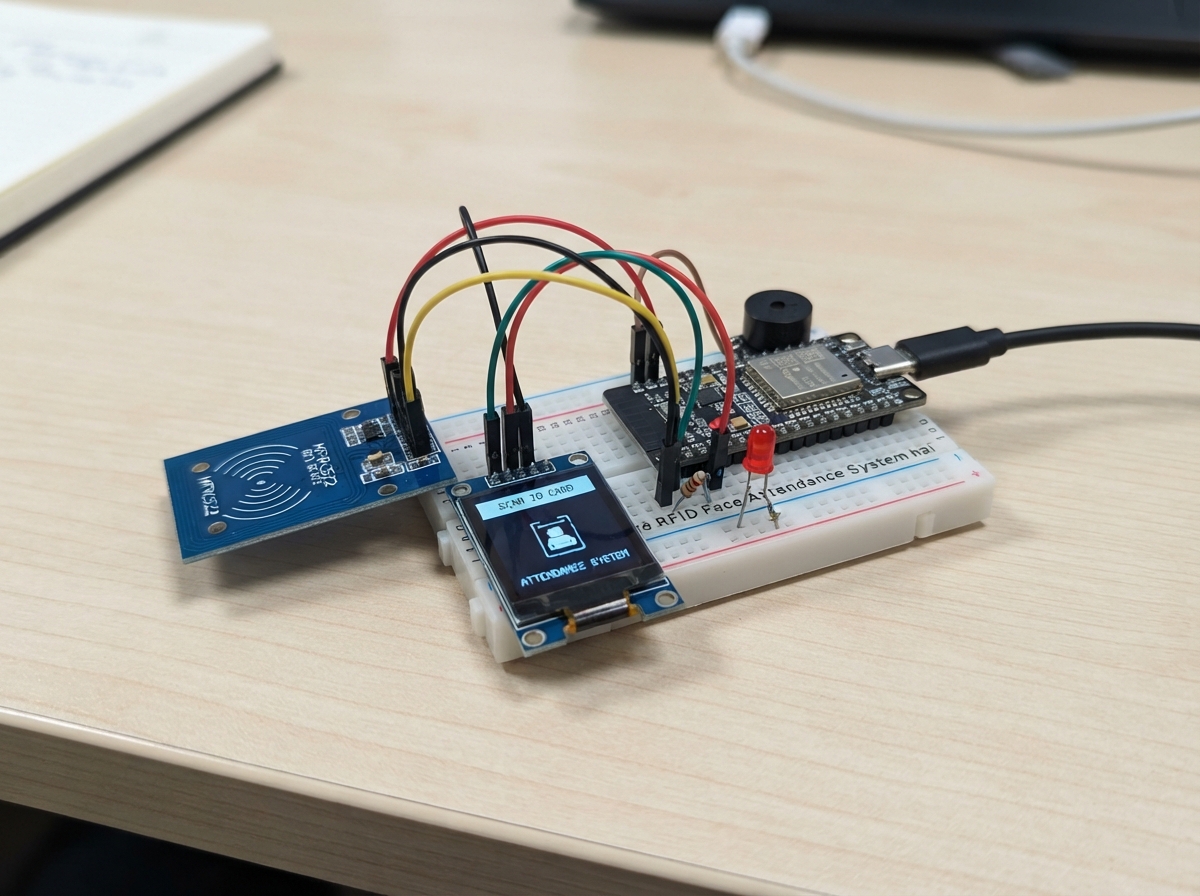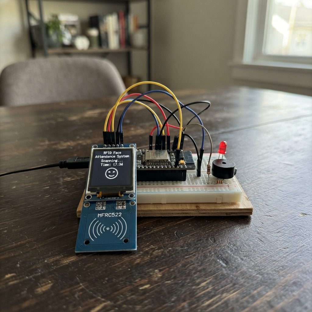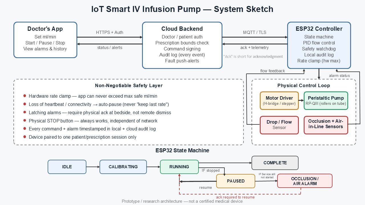
This project demonstrates a water-only bench rig for an IoT-enabled peristaltic pump system built around an ESP32 microcontroller. The setup integrates motor control via a DRV8833 driver, real-time monitoring with an HX710B pressure sensor and TCRT5000 line tracker, and safety features including a hardware-only STOP button override and audible alarm. Builders will receive a complete wiring diagram, parts list, step-by-step assembly instructions, and firmware code that handles PWM pump speed control, sensor integration, and emergency shutdown logic.
This bench demonstration is designed for supervised testing and development only—not for medical or human use. The guide walks through motor regulator configuration, power rail setup, sensor wiring at 3.3 V logic levels, and a powered checkout procedure to verify the motor path and control logic before operation.
Wiring diagram
Gather all the parts
Assemble it in 9 steps
1. Keep this as a supervised water-only bench rig
Arrange the ESP32, modules, and tubing on a dry bench. Send water only into a measuring cup; never connect this prototype to a person or any human-use tubing.
- This is not a medical device or a certified safety system.
2. Set the motor regulator before joining the pump
With the pump disconnected, connect the USB adapter 5 V output to motor_regulator VIN+ (power) and its GND to VIN− (ground). Turn the regulator adjustment until a meter reads exactly 3.0 V between VOUT+ and VOUT−. Do not connect the pump until this reading is correct.
- A regulator set above 3.0 V can damage the 3 V pump.
- Do not set the voltage by guesswork; measure it first.
3. Make the shared ground and motor-power rail
Connect ESP32 GND, motor_regulator VOUT−, DRV8833 GND, sensors, screen, button, LED, and buzzer-transistor emitter to the same ground rail (ground). Connect motor_regulator VOUT+ to DRV8833 VM (3.0 V motor power). Put both the 100 µF capacitor and 0.1 µF capacitor between VM and GND beside the driver: each capacitor’s negative side goes to GND.
- Never connect the DRV8833 VM pin or the 3 V pump to 5 V.
- The 100 µF capacitor striped lead goes to GND; reversed polarity can damage it.
4. Wire the DRV8833 and pump
Use a DRV8833 screw-terminal module that exposes nSLEEP or EN. Connect AIN1 to GPIO27 (speed signal), AIN2 to GPIO26 (direction signal), BIN1 and BIN2 to GND (unused channel held off), AOUT1 to pump MOTOR+ (motor power), and AOUT2 to pump MOTOR− (motor power). Leave BOUT1 and BOUT2 unconnected. GPIO25 is no longer used by the motor driver.
- Do not connect the pump directly to an ESP32 pin.
- Do not buy a DRV8833 module that hides nSLEEP or EN; the physical Stop button must disable this pin.
5. Wire the STOP-only hardware override
Connect one normally-open button leg to GND (ground). Join its other leg to GPIO33 and the DRV8833 nSLEEP/EN terminal (stop signal). Connect the 10 kΩ resistor from this same junction to ESP32 3V3 (pull-up power). Pressing the button pulls nSLEEP low and disables the driver in hardware; it never starts a run.
- A permanently low nSLEEP/EN line prevents all motor motion.
6. Wire the sensors and display at 3.3 V
Connect drop sensor VCC to 3V3 (power), GND to GND (ground), and DO to GPIO32 (drop signal). Connect pressure sensor VCC to 3V3 (power), GND to GND (ground), DOUT to GPIO13 (data), and SCK to GPIO14 (clock). Connect OLED VCC to 3V3 (power), GND to GND (ground), SDA to GPIO21 (data), and SCL to GPIO22 (clock).
- Do not feed 5 V into GPIO32; the drop-sensor output must stay at ESP32-safe 3.3 V.
- Keep water out of the pressure port.
7. Wire the alarm outputs
Connect GPIO4 through the 220 Ω resistor to the LED long leg (alarm signal) and its short leg to GND. Connect GPIO23 through the 1 kΩ resistor to the verified transistor base (signal), emitter to GND, collector to buzzer negative, and buzzer positive to 5 V. Put the 1N5819 striped end at 5 V and its unstriped end at the collector/buzzer-negative junction.
- Check the actual transistor package pinout; 2N2222 and BC547 lead order is not interchangeable.
8. Wire the speed-limit knob
Connect one outer potentiometer leg to 3V3 (power), the other outer leg to GND (ground), and the centre wiper to GPIO34 (speed-limit signal). This knob changes only the controller speed limit and must not carry pump current.
- Never put the potentiometer in series with the pump supply.
9. Perform the first powered check
With the tube in water and the outlet aimed into a cup, confirm that the motor regulator still measures 3.0 V between VM and GND. Then plug in the ESP32 over USB. Press the physical STOP button while the demo is running; it must immediately disable the driver. Use the local page only after this physical check.
- If the regulator voltage sags or the adapter shuts down when the pump starts, stop testing; the pump startup and stall current remains unverified.
Review all connections
1. Connections between "driver" and "ESP32"
2. Connections between "stop_button" and "ESP32"
3. Connections between "r2_stop_pullup" and "ESP32"
4. Connections between "c1_logic" and "ESP32"
5. Connections between "c2_motor" and "ESP32"
6. Connections between "motor_regulator" and "ESP32"
7. Connections between "power_supply" and "ESP32"
8. Connections between "ir_drop_sensor" and "ESP32"
9. Connections between "pressure_sensor_hx710b" and "ESP32"
10. Connections between "speed_pot" and "ESP32"
11. Connections between "oled_display" and "ESP32"
12. Connections between "r3_led" and "ESP32"
13. Connections between "alarm_led" and "ESP32"
14. Connections between "buzzer" and "ESP32"
15. Connections between "q1_buzzer" and "ESP32"
16. Connections between "r6_buzzer_base" and "ESP32"
17. Connections between "d1_buzzer" and "ESP32"
Deploy the firmware
/*
  Water-only bench pump demo.
  Not for medical or human use.

  The pump starts at a fixed moderate speed after boot.
  The physical red STOP button only stops the pump; it never starts it.
  Restart the ESP32 to run the demo again after pressing STOP.
*/
#include <Arduino.h>

// DRV8833 channel A has no separate PWM enable pin.
// GPIO27 drives AIN1 with PWM; GPIO26 holds AIN2 LOW for forward drive.
constexpr int AIN2_PIN = 26;
constexpr int PUMP_PWM_PIN = 27;
constexpr int STOP_PIN = 33;

constexpr uint32_t PWM_FREQ_HZ = 18000;
constexpr uint8_t PWM_BITS = 8;
// Full duty is used only to prove the motor power path in this bench demo.
constexpr uint8_t DEMO_PWM = 255;

bool stopped = false;

bool stopPressed() {
  // The button has the existing external 10 kΩ pull-up, so LOW means pressed.
  return digitalRead(STOP_PIN) == LOW;
}

void stopPump() {
  ledcWrite(PUMP_PWM_PIN, 0);
  digitalWrite(AIN2_PIN, LOW);
  stopped = true;
}

void setup() {
  pinMode(AIN2_PIN, OUTPUT);
  pinMode(STOP_PIN, INPUT);
  ledcAttach(PUMP_PWM_PIN, PWM_FREQ_HZ, PWM_BITS);

  stopPump();

  // Do not start if the physical STOP button is already held down.
  if (!stopPressed()) {
    digitalWrite(AIN2_PIN, LOW);
    ledcWrite(PUMP_PWM_PIN, DEMO_PWM);
    stopped = false;
  }
}

void loop() {
  // Once stopped, it remains stopped until the ESP32 is restarted.
  if (!stopped && stopPressed()) {
    stopPump();
  }
  delay(10);
}
Remix this project
Make it yours in one click
Open a full copy of this project in your own Schematik workspace, diagram, code, parts, and assembly steps included. Swap the sensor, add features, or redesign the whole thing with AI. The author's original stays untouched.