Community project
Master Build Specification Turbine/edf Hybrid Fp
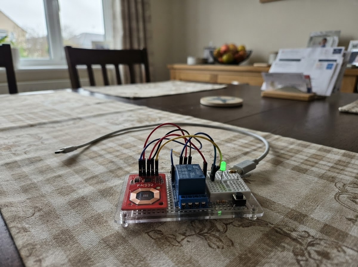
This project builds an NFC-based access control system for a turbine or EDF hybrid flight platform using an ESP32 microcontroller. The system uses an NFC reader to authenticate approved tags, controlling an opto-isolated relay that gates the engine enable signal. The guide provides a complete wiring diagram, parts list, and Arduino firmware with tag enrollment and timed unlock features.
Builders will learn how to set up I2C communication with the PN532 NFC module, wire safety-critical relay control with optical isolation, and implement secure tag management in non-volatile storage. The assembly outline keeps the flight system completely separate from the control electronics, with step-by-step instructions for enrollment and ground testing before deployment.
Wiring diagram

Gather all the parts
Assemble it in 6 steps
1. Keep the flight system separate
Mount the Pixhawk 6C, its approved power module, GPS/compass, RC receiver, twin EDF ESCs, and telemetry radio as the electric-only aircraft system. Feed the Pixhawk through its dedicated power-monitor connector, mount the compass away from EDF wiring, and use two separate ESC outputs for the two EDFs. Do not route any turbine ECU start wire through the Pixhawk, receiver, or EDF power circuit; this NFC module is only a separate permission switch for the future turbine ECU start-enable input.
- Prove RTL, geofence, RC-loss response, battery monitoring, and both EDFs on the electric-only airframe before installing the turbine.
- Mount the flight controller on vibration-damping foam with its arrow pointing forward.
- Do not use the NFC relay as a flight-control or battery-power cutoff. Losing NFC-module power must not stop the EDFs or remove ArduPilot power in flight.
- A turbine ECU wiring diagram varies by model; use only the manufacturer-documented low-current external start-enable loop for the relay contacts.
2. Set the NFC reader to I2C mode
On pn532_1, set both interface switches to ON for I2C mode before applying power. Connect VCC → ESP32 3V3 (power), GND → ESP32 GND (ground), SDA → GPIO21 (data), and SCL → GPIO22 (data). Leave IRQ and RSTO unconnected.
- Keep the reader antenna facing an accessible non-metallic hatch so a tag can be tapped through the airframe skin.
- Use short twisted or paired SDA/GND and SCL/GND wires if the reader is more than a few centimetres from the ESP32.
- Do not connect the PN532 VCC to 5 V in this design — 5 V on its signal lines can damage the ESP32.
3. Wire the lock button and light
Connect lock_button_1 SIG → GPIO32 (signal) and its other leg GND → ESP32 GND (ground). Connect GPIO26 → led_resistor_1 END_A (signal), led_resistor_1 END_B → status_led_1 long leg/anode (current-limited signal), and the LED short leg/flat-side cathode → GND (ground).
- The 220 Ω resistor can go on either side of the LED, but it must remain in series with it.
- The green LED stays off while the turbine-start circuit is locked and lights only during the 60-second authorization window.
- Never connect an LED directly from GPIO26 to ground without the 220 Ω resistor — excessive current can damage the LED or ESP32 pin.
4. Wire the isolated relay control
Connect relay_1 VCC → regulated 5 V (power), relay_1 GND → the 5 V supply ground and ESP32 GND (shared reference), and relay_1 IN → GPIO27 (control signal). Use a regulated 5 V supply that can run the ESP32 through its VIN/5V pin and the relay; power the PN532 only from ESP32 3V3.
- Before connecting the ECU, listen for one relay click when you tap the approved NFC tag; another click occurs when it locks or times out.
- Place this electronics assembly in a protected bay, well away from turbine heat, tailpipe radiation, fuel lines, and high-current EDF battery leads.
- Check the relay board’s input behavior with a multimeter before connecting an ECU: some relay modules are active-low. If yours operates backwards, change RELAY_ON_LEVEL and RELAY_OFF_LEVEL in the firmware before use.
- Do not power a relay coil from the ESP32 3V3 pin; its current demand can brown out the ESP32.
5. Connect only the approved ECU enable loop
With all aircraft power disconnected, connect relay_1 COM → one side of the exact manufacturer-approved external ECU start-enable loop (enable), and relay_1 NO → the other side of that same loop (enable). The normally-open contact must leave the loop broken when the ESP32 is unpowered, booting, locked, or has timed out.
- Use a continuity meter first: locked should show open circuit between COM and NO; an authorized tag should show a closed contact for up to 60 seconds.
- Do the first tests with fuel removed and the turbine disconnected from its fuel feed.
- Never put this relay in the ECU main battery cable, starter-power cable, glow/ignition lead, fuel-pump power lead, or any unknown ECU wire. Incorrect turbine wiring can cause an uncommanded start, fire, equipment damage, or serious injury.
6. Enroll and test the tag while parked
Power the lock module by USB for the first firmware deployment. Press Deploy in Schematik. With the module safely parked and the turbine system disconnected, hold lock_button_1 for three seconds, then tap the tag you want to authorize. The serial status will confirm that the tag was saved; a normal short button press locks immediately. Tap the approved tag to close the relay for 60 seconds, then confirm it opens again automatically.
- Keep the approved tag secured separately from the aircraft when it is stored.
- Repeat the power-up check: after every restart, the relay must remain open until a recognized tag is tapped.
- Do not perform tag enrollment or relay tests with turbine fuel connected, a starter armed, or people in the turbine intake/exhaust area.
Review all connections
1. Connections between "pn532_1" and "ESP32"
2. Connections between "relay_1" and "ESP32"
3. Connections between "lock_button_1" and "ESP32"
4. Connections between "led_resistor_1" and "ESP32"
5. Connections between "status_led_1" and "ESP32"
Deploy the firmware
#include <Arduino.h>
#include <Wire.h>
#include <Adafruit_PN532.h>
#include <Preferences.h>


// Forward declarations
String uidToHex(const uint8_t *uid, uint8_t uidLength);
void lockTurbineEnable();
void unlockTurbineEnable();
void handleButton();
void handleTag();

constexpr uint8_t RELAY_PIN = 27;
constexpr uint8_t STATUS_LED_PIN = 26;
constexpr uint8_t LOCK_BUTTON_PIN = 32;
constexpr uint8_t I2C_SDA_PIN = 21;
constexpr uint8_t I2C_SCL_PIN = 22;
constexpr bool RELAY_ON_LEVEL = HIGH;
constexpr bool RELAY_OFF_LEVEL = LOW;
constexpr uint32_t UNLOCK_TIME_MS = 60000;
constexpr uint32_t ENROLL_HOLD_MS = 3000;
constexpr uint32_t BUTTON_DEBOUNCE_MS = 35;

Adafruit_PN532 nfc(&Wire);
Preferences preferences;

bool readerReady = false;
bool unlocked = false;
bool enrollmentMode = false;
uint32_t unlockStartedMs = 0;
uint32_t buttonPressedMs = 0;
uint32_t lastButtonChangeMs = 0;
bool lastButtonReading = HIGH;
bool stableButtonState = HIGH;

String uidToHex(const uint8_t *uid, uint8_t uidLength) {
  String value;
  for (uint8_t i = 0; i < uidLength; ++i) {
    if (uid[i] < 0x10) value += '0';
    value += String(uid[i], HEX);
  }
  value.toUpperCase();
  return value;
}

void lockTurbineEnable() {
  digitalWrite(RELAY_PIN, RELAY_OFF_LEVEL);
  digitalWrite(STATUS_LED_PIN, LOW);
  unlocked = false;
  enrollmentMode = false;
  Serial.println("Turbine start enable: LOCKED");
}

void unlockTurbineEnable() {
  digitalWrite(RELAY_PIN, RELAY_ON_LEVEL);
  digitalWrite(STATUS_LED_PIN, HIGH);
  unlockStartedMs = millis();
  unlocked = true;
  enrollmentMode = false;
  Serial.println("Turbine start enable: UNLOCKED for 60 seconds");
}

void handleButton() {
  const bool reading = digitalRead(LOCK_BUTTON_PIN);
  const uint32_t now = millis();

  if (reading != lastButtonReading) lastButtonChangeMs = now;
  lastButtonReading = reading;

  if (now - lastButtonChangeMs >= BUTTON_DEBOUNCE_MS && reading != stableButtonState) {
    stableButtonState = reading;
    if (stableButtonState == LOW) {
      buttonPressedMs = now;
    } else {
      const uint32_t heldMs = now - buttonPressedMs;
      if (heldMs < ENROLL_HOLD_MS) {
        lockTurbineEnable();
      }
    }
  }

  if (stableButtonState == LOW && !enrollmentMode && now - buttonPressedMs >= ENROLL_HOLD_MS) {
    lockTurbineEnable();
    enrollmentMode = true;
    Serial.println("Enrollment mode: tap a tag within 30 seconds");
  }
}

void handleTag() {
  if (!readerReady) return;

  uint8_t uid[7] = {0};
  uint8_t uidLength = 0;
  if (!nfc.readPassiveTargetID(PN532_MIFARE_ISO14443A, uid, &uidLength, 80)) return;

  const String scannedUid = uidToHex(uid, uidLength);
  Serial.print("NFC tag detected: ");
  Serial.println(scannedUid);

  if (enrollmentMode) {
    preferences.putString("tag_uid", scannedUid);
    Serial.println("Approved tag saved. Turbine start remains locked.");
    enrollmentMode = false;
    delay(500);
    return;
  }

  const String approvedUid = preferences.getString("tag_uid", "");
  if (approvedUid.length() == 0) {
    Serial.println("No approved tag. Hold the lock button for 3 seconds to enroll one while parked.");
  } else if (scannedUid == approvedUid) {
    unlockTurbineEnable();
  } else {
    Serial.println("Unrecognized tag. Turbine start remains locked.");
  }
  delay(500);
}

void setup() {
  pinMode(RELAY_PIN, OUTPUT);
  pinMode(STATUS_LED_PIN, OUTPUT);
  pinMode(LOCK_BUTTON_PIN, INPUT_PULLUP);
  lockTurbineEnable();

  Serial.begin(115200);
  Wire.begin(I2C_SDA_PIN, I2C_SCL_PIN);
  preferences.begin("nfc-lock", false);

  nfc.begin();
  const uint32_t version = nfc.getFirmwareVersion();
  if (version == 0) {
    Serial.println("PN532 not found. Relay remains locked.");
    readerReady = false;
    return;
  }

  nfc.SAMConfig();
  readerReady = true;
  Serial.println("NFC lock ready. Relay is locked until an approved tag is tapped.");
}

void loop() {
  handleButton();

  if (unlocked && millis() - unlockStartedMs >= UNLOCK_TIME_MS) {
    lockTurbineEnable();
  }

  handleTag();
}
Remix this project
Make it yours in one click
Open a full copy of this project in your own Schematik workspace — diagram, code, parts, and assembly steps included. Swap the sensor, add features, or redesign the whole thing with AI. The author's original stays untouched.