Community project
Nine-LED Light Chase
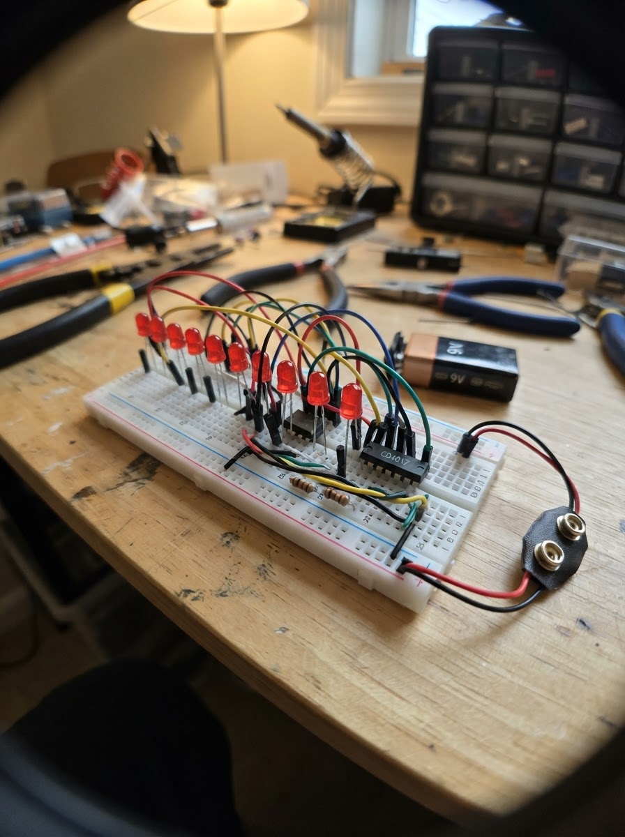
This project creates a mesmerizing light chase effect using nine LEDs controlled by an Arduino Uno. The LEDs fade smoothly from one to the next in sequence, creating a flowing pattern that cycles continuously around the array.
The guide provides a complete parts list, wiring diagram showing how to connect each LED with its current-limiting resistor to the Arduino's digital pins, and the firmware needed to generate the smooth fade transitions. Assembly takes about 30 minutes and requires only basic soldering skills or breadboard connections.
Wiring diagram

Gather all the parts
Assemble it in 5 steps
1. Arduino und Steckbrett vorbereiten
Lege den Arduino Uno neben das Steckbrett und verbinde einen GND-Anschluss des Arduino mit der blauen oder minus-markierten Sammelschiene des Steckbretts. Diese gemeinsame Leitung ist der Rückweg für alle neun LEDs.
- Nimm für die GND-Verbindung am besten ein schwarzes Jumperkabel.
- Die lange Sammelschiene darfst du für alle kurzen LED-Beine gemeinsam verwenden.
- Stecke den Arduino beim Umbauen noch nicht per USB an, damit sich lose Drähte nicht versehentlich berühren.
2. Neun LEDs einsetzen
Stecke led_1 bis led_9 nebeneinander in das Steckbrett. Bei jeder LED zeigt das längere Bein nach vorne zum jeweiligen Widerstand; das kürzere Bein kommt jeweils in eine eigene Reihe, die du mit der GND-Sammelschiene verbindest.
- Das kurze Bein ist meist auch auf der abgeflachten Seite des LED-Gehäuses.
- Achte darauf, dass die beiden Beine einer LED nicht in derselben verbundenen Steckbrettreihe stecken.
- Wenn langes und kurzes Bein vertauscht sind, leuchtet die LED nicht.
3. Widerstände vor die LEDs setzen
Stecke je einen 220-Ω-Widerstand zwischen das lange Bein jeder LED und eine freie Steckbrettreihe. Verbinde resistor_1 mit led_1, resistor_2 mit led_2 und so weiter bis resistor_9 mit led_9. Ein Widerstand darf in beide Richtungen eingebaut werden.
- Bei 220 Ω sind die Farbringe meist rot–rot–braun; die Toleranzfarbe kann unterschiedlich sein.
- Jede LED braucht ihren eigenen Widerstand.
- Verbinde eine LED nie direkt mit einem Arduino-Pin — ohne Widerstand kann zu viel Strom fließen und LED oder Arduino beschädigen.
4. Die neun Steuersignale anschließen
Verbinde die freien Widerstandsenden mit den digitalen Pins des Arduino: resistor_1 → D2, resistor_2 → D3, resistor_3 → D4, resistor_4 → D5, resistor_5 → D6, resistor_6 → D7, resistor_7 → D8, resistor_8 → D9 und resistor_9 → D10. Diese Drähte sagen jeweils einer LED, wann sie leuchten soll.
- Du kannst für die neun Signale verschiedene Kabelfarben nehmen und sie von links nach rechts nummerieren.
- D0 und D1 bleiben frei, damit das Aufspielen des Programms zuverlässig funktioniert.
- Prüfe besonders, dass kein Widerstandsende versehentlich an 5V statt an D2 bis D10 steckt; dann wäre die zugehörige LED dauerhaft an.
5. Stromversorgung und erster Test
Prüfe nochmals: Alle kurzen LED-Beine führen zur GND-Sammelschiene, jede lange Seite führt erst durch ihren eigenen Widerstand zu D2 bis D10. Danach verbindest du den Arduino Uno per USB mit dem Computer.
- Nach dem Übertragen des Programms leuchtet immer genau eine LED; sie wechselt alle Viertelsekunde zur nächsten.
- Wenn eine Position übersprungen wird, kontrolliere zuerst die Richtung dieser LED und ihren Widerstand.
- Schalte die USB-Verbindung ab, bevor du vertauschte Drähte umsteckst — so vermeidest du einen Kurzschluss.
Review all connections
1. Connections between "resistor_1" and "Arduino"
2. Connections between "led_1" and "Arduino"
3. Connections between "resistor_2" and "Arduino"
4. Connections between "led_2" and "Arduino"
5. Connections between "resistor_3" and "Arduino"
6. Connections between "led_3" and "Arduino"
7. Connections between "resistor_4" and "Arduino"
8. Connections between "led_4" and "Arduino"
9. Connections between "resistor_5" and "Arduino"
10. Connections between "led_5" and "Arduino"
11. Connections between "resistor_6" and "Arduino"
12. Connections between "led_6" and "Arduino"
13. Connections between "resistor_7" and "Arduino"
14. Connections between "led_7" and "Arduino"
15. Connections between "resistor_8" and "Arduino"
16. Connections between "led_8" and "Arduino"
17. Connections between "resistor_9" and "Arduino"
18. Connections between "led_9" and "Arduino"
Deploy the firmware
#include <Arduino.h>


// Forward declarations
void updateBrightness();
void refreshSoftwarePwm();

const byte LED_1_PIN = 2;
const byte LED_2_PIN = 3;
const byte LED_3_PIN = 4;
const byte LED_4_PIN = 5;
const byte LED_5_PIN = 6;
const byte LED_6_PIN = 7;
const byte LED_7_PIN = 8;
const byte LED_8_PIN = 9;
const byte LED_9_PIN = 10;

const byte ledPins[] = {
  LED_1_PIN, LED_2_PIN, LED_3_PIN,
  LED_4_PIN, LED_5_PIN, LED_6_PIN,
  LED_7_PIN, LED_8_PIN, LED_9_PIN
};

const byte LED_COUNT = sizeof(ledPins) / sizeof(ledPins[0]);
const unsigned long FADE_TIME_MS = 250;
const unsigned long PWM_TICK_US = 125;
const byte PWM_STEPS = 16;

byte fadingFrom = 0;
byte fadingTo = 1;
byte brightness[LED_COUNT] = {0};
unsigned long fadeStartedAt;
unsigned long lastPwmTick;
byte pwmPhase = 0;

void updateBrightness() {
  unsigned long elapsed = millis() - fadeStartedAt;
  byte level = (elapsed >= FADE_TIME_MS)
                 ? PWM_STEPS
                 : (byte)((elapsed * PWM_STEPS) / FADE_TIME_MS);

  for (byte i = 0; i < LED_COUNT; i++) {
    brightness[i] = 0;
  }

  brightness[fadingFrom] = PWM_STEPS - level;
  brightness[fadingTo] = level;

  if (elapsed >= FADE_TIME_MS) {
    fadingFrom = fadingTo;
    fadingTo++;
    if (fadingTo >= LED_COUNT) {
      fadingTo = 0;
    }
    fadeStartedAt += FADE_TIME_MS;
  }
}

void refreshSoftwarePwm() {
  unsigned long now = micros();
  if (now - lastPwmTick < PWM_TICK_US) {
    return;
  }

  lastPwmTick = now;
  pwmPhase++;
  if (pwmPhase >= PWM_STEPS) {
    pwmPhase = 0;
  }

  for (byte i = 0; i < LED_COUNT; i++) {
    digitalWrite(ledPins[i], brightness[i] > pwmPhase ? HIGH : LOW);
  }
}

void setup() {
  for (byte i = 0; i < LED_COUNT; i++) {
    pinMode(ledPins[i], OUTPUT);
    digitalWrite(ledPins[i], LOW);
  }

  brightness[fadingFrom] = PWM_STEPS;
  fadeStartedAt = millis();
  lastPwmTick = micros();
}

void loop() {
  updateBrightness();
  refreshSoftwarePwm();
}
Remix this project
Make it yours in one click
Open a full copy of this project in your own Schematik workspace — diagram, code, parts, and assembly steps included. Swap the sensor, add features, or redesign the whole thing with AI. The author's original stays untouched.