Community project
ESP32 Battery Load Tester
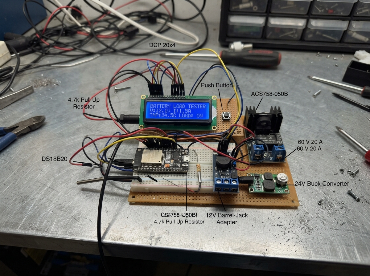
This ESP32 battery load tester applies a controlled electrical load to a battery while measuring voltage, current, and temperature in real time. The tester uses a 5 Ω power resistor as the load, a Hall-effect current sensor to track draw, a DS18B20 temperature sensor to monitor heat, and a solid-state relay to safely switch the load on and off. A 20x4 LCD display shows live readings, and the system automatically shuts down if temperature exceeds safe limits.
This guide provides a complete wiring diagram, full parts list, Arduino firmware, and step-by-step assembly instructions. Builders will learn how to safely handle high-power circuits, integrate multiple sensors with an Arduino, and create a practical tool for testing battery capacity and performance under load.
Wiring diagram

Gather all the parts
Assemble it in 7 steps
1. Mount the hot load safely
Bolt load_resistor firmly to a substantial aluminium heat sink using thermal paste, then aim fan at the fins. Leave the resistor and heat sink uncovered and away from plastic, wire insulation, fingers, and anything that can burn.
- Use short, thick wire rated for at least 10 A in the battery-to-resistor path.
- At 30 V the resistor can make about 180 W of heat. It can cause burns or start a fire if it is not mounted on a heat sink with clear airflow.
2. Make the switched battery load path
With every supply unplugged, connect the test battery positive terminal to current_sensor IP+ (current enters the sensor). Connect current_sensor IP- to load_ssr LOAD+ (switched-load input), load_ssr LOAD- to load_resistor P1 (switched-load output), and load_resistor P2 to the common GND rail and the test battery negative terminal (load return).
- The solid-state relay must be explicitly rated for at least 60 V DC and 20 A DC; do not substitute an AC-only relay.
- Never let the battery positive and negative wires touch. A battery capable of 6 A or more can melt thin wires very quickly.
3. Build the battery-voltage reader
Connect the test battery positive terminal to voltage_divider_top P1 (measurement input). Connect voltage_divider_top P2 to Arduino A0 and to voltage_divider_bottom P1 (safe reduced-voltage junction). Connect voltage_divider_bottom P2 to GND (measurement return).
- Keep these small measurement wires away from the thick high-current load wires.
- Do not connect the test battery positive terminal directly to A0 — more than 5 V can permanently damage the Arduino.
4. Power the control side
Connect control_supply +12V to the 12V rail and control_supply GND to the common GND rail (power). Set logic_buck to exactly 5.0 V before connecting the Arduino, then connect its VIN+ to 12V, VIN- to GND, VOUT+ to the Arduino 5V rail, and VOUT- to GND (logic power).
- Measure the buck output with a multimeter first; turn its small adjustment screw until it reads 5.0 V.
- Do not feed 12 V into the Arduino 5V pin — it can damage the board.
5. Wire the display, temperature sensor, and start button
Connect lcd VCC to 5V (power), lcd GND to GND (ground), lcd SDA to Arduino A4/GPIO18 (data), and lcd SCL to Arduino A5/GPIO19 (clock). Put temp_sensor against the resistor body or heat sink with a metal clamp, then connect VCC to 3.3V (power), GND to GND (ground), and DATA to D2/GPIO2 (temperature signal). Connect onewire_pullup between 3.3V and that same D2/DATA wire (keeps the signal readable). Connect start_button SIGNAL to D3/GPIO3 (start signal) and its other pin to GND (ground).
- The sensor must touch the resistor or heat sink; measuring nearby air will not provide a useful safety cutoff.
- Make sure LCD VCC and GND are not swapped — swapped power can damage the screen.
6. Connect the relay, fan, and alarm controls
Connect load_ssr VCC to 5V (control power), GND to GND (control return), and IN to D8/GPIO8 (load-switch command). Connect fan +12V to 12V (power) and its GND to fan_switch LOAD- (switched return); then connect fan_switch VCC to 5V, GND to GND, and IN to D9/GPIO9 (fan command). Connect buzzer_12v +12V to 12V (power) and GND to buzzer_switch LOAD- (switched return); then connect buzzer_switch VCC to 5V, GND to GND, and IN to D10/GPIO10 (alarm command).
- All control-side grounds, including the Arduino, current sensor, buck converter, and 12 V supply, must join the same GND rail.
- Do not connect the 12 V fan or 12 V piezo directly to an Arduino pin — their current can damage the board.
7. Check before a real battery test
First power only the 12 V control supply and use the LCD to confirm the temperature looks sensible. With no test battery connected, press the button and confirm the relay changes state briefly. Then connect a battery that is no more than 30 V, keep clear of the heat sink, and press START once; a quick tap counts exactly once.
- The fan should start at 25 C, the load should open at 40 C, and the alarm sounds through the last five seconds of a normal 60-second test.
- Stay with the tester while it is running. If the resistor reaches 40 C, the test stops and the alarm remains on until you start a new test after it cools.
Review all connections
1. Connections between "control_supply" and "Arduino"
2. Connections between "logic_buck" and "Arduino"
3. Connections between "temp_sensor" and "Arduino"
4. Connections between "onewire_pullup" and "Arduino"
5. Connections between "lcd" and "Arduino"
6. Connections between "start_button" and "Arduino"
7. Connections between "current_sensor" and "Arduino"
8. Connections between "load_ssr" and "Arduino"
9. Connections between "load_resistor" and "Arduino"
10. Connections between "voltage_divider_top" and "Arduino"
11. Connections between "voltage_divider_bottom" and "Arduino"
12. Connections between "fan" and "Arduino"
13. Connections between "fan_switch" and "Arduino"
14. Connections between "buzzer_12v" and "Arduino"
15. Connections between "buzzer_switch" and "Arduino"
Deploy the firmware
#include <Wire.h>
#include <LiquidCrystal_I2C.h>
#include <OneWire.h>
#include <DallasTemperature.h>
#include <math.h>

const uint8_t ONEWIRE_PIN = 2;
const uint8_t START_BUTTON_PIN = 3;
const uint8_t SSR_PIN = 8;
const uint8_t FAN_PIN = 9;
const uint8_t BUZZER_PIN = 10;
const uint8_t VOLTAGE_PIN = A0;
const uint8_t CURRENT_PIN = A1;

const unsigned long TEST_DURATION_MS = 60000UL;
const float FAN_ON_C = 25.0f;
const float FAN_OFF_C = 23.0f;
const float CUTOFF_C = 40.0f;
const float ADC_REFERENCE_V = 5.0f;
const float DIVIDER_RATIO = (100.0f + 18.0f) / 18.0f;
// ACS758-050B: nominal 0.60 V at 0 A and 40 mV/A. Calibrate if your module differs.
const float CURRENT_ZERO_V = 0.60f;
const float CURRENT_SENSITIVITY_V_PER_A = 0.040f;

LiquidCrystal_I2C lcd(0x20, 20, 4);
OneWire oneWire(ONEWIRE_PIN);
DallasTemperature temperatureBus(&oneWire);

bool testActive = false;
bool overTempAlarm = false;
bool fanOn = false;
unsigned long testStartedMs = 0;
unsigned long lastButtonChangeMs = 0;
bool lastRawButton = HIGH;
bool stableButton = HIGH;
unsigned long lastDisplayMs = 0;
String previousLine[4] = {"", "", "", ""};

float readAverageVoltage(uint8_t pin) {
  unsigned long total = 0;
  for (uint8_t i = 0; i < 16; ++i) {
    total += analogRead(pin);
  }
  return (total / 16.0f) * ADC_REFERENCE_V / 1023.0f;
}

float readBatteryVoltage() {
  return readAverageVoltage(VOLTAGE_PIN) * DIVIDER_RATIO;
}

float readCurrentA() {
  float amps = (readAverageVoltage(CURRENT_PIN) - CURRENT_ZERO_V) / CURRENT_SENSITIVITY_V_PER_A;
  return (amps < 0.0f) ? 0.0f : amps;
}

void printLine(uint8_t row, String text) {
  while (text.length() < 20) text += ' ';
  if (text.length() > 20) text.remove(20);
  if (text != previousLine[row]) {
    lcd.setCursor(0, row);
    lcd.print(text);
    previousLine[row] = text;
  }
}

void updateDisplay(float batteryV, float currentA, float temperatureC, unsigned long secondsLeft) {
  if (millis() - lastDisplayMs < 250UL) return;
  lastDisplayMs = millis();
  printLine(0, String("Battery: ") + String(batteryV, 2) + " V");
  printLine(1, String("Current: ") + String(currentA, 2) + " A");
  printLine(2, String("Time left: ") + String(secondsLeft) + " s");
  if (isnan(temperatureC)) {
    printLine(3, "Resistor: sensor err");
  } else {
    printLine(3, String("Resistor: ") + String(temperatureC, 1) + " C");
  }
}

bool startButtonPressed() {
  bool raw = digitalRead(START_BUTTON_PIN);
  if (raw != lastRawButton) lastButtonChangeMs = millis();
  lastRawButton = raw;
  if ((millis() - lastButtonChangeMs) > 35UL && raw != stableButton) {
    stableButton = raw;
    return stableButton == LOW;
  }
  return false;
}

void setup() {
  pinMode(START_BUTTON_PIN, INPUT_PULLUP);
  pinMode(SSR_PIN, OUTPUT);
  pinMode(FAN_PIN, OUTPUT);
  pinMode(BUZZER_PIN, OUTPUT);
  digitalWrite(SSR_PIN, LOW);
  digitalWrite(FAN_PIN, LOW);
  digitalWrite(BUZZER_PIN, LOW);

  lcd.init();
  lcd.backlight();
  temperatureBus.begin();
  temperatureBus.setResolution(10);
  lcd.setCursor(0, 0);
  lcd.print("30V Battery Tester");
  lcd.setCursor(0, 1);
  lcd.print("Press START to test");
}

void loop() {
  temperatureBus.requestTemperatures();
  float resistorTempC = temperatureBus.getTempCByIndex(0);
  if (resistorTempC == DEVICE_DISCONNECTED_C) resistorTempC = NAN;
  float batteryV = readBatteryVoltage();
  float currentA = readCurrentA();

  if (!isnan(resistorTempC)) {
    if (resistorTempC >= FAN_ON_C) fanOn = true;
    if (resistorTempC <= FAN_OFF_C) fanOn = false;
    if (resistorTempC >= CUTOFF_C) {
      testActive = false;
      overTempAlarm = true;
    }
  } else {
    testActive = false; // A missing temperature reading is a safety stop.
    overTempAlarm = true;
  }

  if (startButtonPressed() && !isnan(resistorTempC) && resistorTempC < CUTOFF_C) {
    testActive = true;
    overTempAlarm = false;
    testStartedMs = millis();
  }

  unsigned long elapsedMs = testActive ? (millis() - testStartedMs) : 0UL;
  if (testActive && elapsedMs >= TEST_DURATION_MS) {
    testActive = false;
    elapsedMs = TEST_DURATION_MS;
  }

  unsigned long secondsLeft = 0;
  if (testActive) secondsLeft = (TEST_DURATION_MS - elapsedMs + 999UL) / 1000UL;
  bool finalWarning = testActive && elapsedMs >= (TEST_DURATION_MS - 5000UL);

  digitalWrite(SSR_PIN, testActive ? HIGH : LOW);
  digitalWrite(FAN_PIN, fanOn ? HIGH : LOW);
  digitalWrite(BUZZER_PIN, (finalWarning || overTempAlarm) ? HIGH : LOW);
  updateDisplay(batteryV, currentA, resistorTempC, secondsLeft);
}
Remix this project
Make it yours in one click
Open a full copy of this project in your own Schematik workspace — diagram, code, parts, and assembly steps included. Swap the sensor, add features, or redesign the whole thing with AI. The author's original stays untouched.