Community project
Oximetro Web Con ESP32
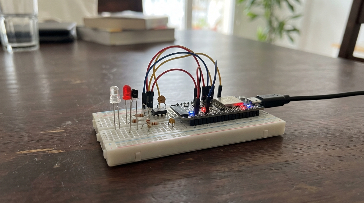
This project builds an educational pulse oximeter using an ESP32 microcontroller and optical sensors to measure heart rate and blood oxygen saturation. The device uses infrared and red LEDs to detect blood flow changes through the fingertip, with a phototransistor capturing the reflected light and an MCP6002 amplifier processing the signal for analysis.
The guide provides a complete wiring diagram, parts list, and step-by-step assembly instructions for building the finger clip sensor and connecting it to the ESP32. Firmware code enables real-time measurement display via a web interface, with the device calculating pulse rate and SpO2 estimates from the optical data. This is an educational project for learning about biosensors and signal processing—it is not suitable for medical diagnosis or treatment decisions.
Wiring diagram

Gather all the parts
Assemble it in 7 steps
1. Desconecta el ESP32 antes de cablear
Desenchufa el cable USB antes de mover cables. Coloca el ESP32 sobre una superficie no metálica y deja visible la hilera de pines con GPIO25, GPIO26, GPIO36, 3V3 y GND.
- GPIO36 también puede estar marcado como VP en la placa.
- No alimentes el circuito mientras cambias conexiones; un cable suelto puede tocar 3V3 y GND y calentar la placa.
2. Monta el LED infrarrojo
Conecta GPIO25 al primer resistor de 220 Ω; conecta el otro extremo del resistor al ánodo del LED infrarrojo. Conecta el cátodo del LED infrarrojo a GND. El ánodo suele ser la pata más larga; el cátodo suele estar junto al lado plano del LED.
- GPIO25 → resistor de 220 Ω (limita la corriente), resistor → ánodo IR (iluminación), cátodo IR → GND (retorno).
- No conectes el LED directamente a GPIO25: sin el resistor puede dañarse el LED o la salida del ESP32.
3. Monta el LED rojo adicional
Conecta GPIO26 al segundo resistor de 220 Ω; conecta el otro extremo del resistor al ánodo del LED rojo de 660 nm. Conecta su cátodo a GND. Pon este LED junto al infrarrojo, ambos apuntando hacia el mismo punto del dedo.
- GPIO26 → resistor de 220 Ω (limita la corriente), resistor → ánodo rojo (iluminación), cátodo rojo → GND (retorno).
- El programa enciende solamente un LED cada vez para comparar ambas luces.
- No intercambies las patas del LED rojo: conectado al revés no ilumina y no habrá una estimación útil.
4. Conecta el detector y el filtro
Conecta el colector del fototransistor a 3V3. Une su emisor al extremo de entrada del resistor de 100 kΩ y al extremo de entrada del capacitor de 100 nF. Conecta los otros extremos del resistor y del capacitor a GND. Ese punto compartido es la señal óptica.
- Colector → 3V3 (alimentación), emisor → nodo de señal (medición), resistor de 100 kΩ → GND (convierte luz en voltaje), capacitor de 100 nF → GND (reduce ruido).
- Comprueba el dibujo o la hoja de datos del fototransistor que tengas: sus patas no siempre siguen el mismo orden.
- No adivines las patas del fototransistor; invertir colector y emisor puede dejar la señal casi plana.
5. Conecta el amplificador y la entrada del ESP32
Alimenta el MCP6002 con VDD a 3V3 y VSS a GND. Conecta el nodo de señal a IN+A. Une IN−A con OUTA y conecta OUTA a GPIO36. Deja el segundo amplificador como está: IN+B e IN−B a GND y OUTB sin usar.
- VDD → 3V3 (alimentación), VSS → GND (retorno), IN+A → nodo de señal (entrada), IN−A unido a OUTA (seguidor), OUTA → GPIO36 (lectura analógica).
- Consulta la muesca o punto del encapsulado MCP6002 para localizar el pin 1 antes de enchufarlo.
- No intercambies VDD y VSS: alimentar el MCP6002 al revés puede dañarlo.
6. Construye la pinza para el dedo
Sujeta los dos LEDs en una cara de una pinza de ropa y el fototransistor mirando de frente desde la cara opuesta. Deja un hueco suave para la yema del dedo. Cubre las paredes internas con cinta negra para que la luz de la habitación no llegue directamente al detector.
- Los LEDs → dedo (iluminación), fototransistor enfrente → dedo (detección).
- No aprietes el dedo: una presión fuerte cambia el flujo de sangre y empeora la señal.
- No mires fijamente el LED infrarrojo a corta distancia: su luz no se ve, pero sigue siendo luz intensa para los ojos.
7. Haz la medición
Coloca la yema del dedo quieta dentro de la pinza, lejos de luz solar directa. Conecta el ESP32 por USB, pulsa Deploy y abre la página de la red Wi‑Fi PPG-Monitor. Espera al menos 10 segundos con el dedo inmóvil para que aparezcan las estimaciones.
- La web muestra la forma de onda, los latidos por minuto y una estimación experimental de SpO₂.
- Si la lectura salta mucho, bloquea mejor la luz exterior y afloja la pinza.
- No uses esta estimación para diagnóstico, triaje ni decisiones médicas; este circuito no tiene la calibración ni validación de un oxímetro certificado.
Review all connections
1. Connections between "r_led_220" and "ESP32"
2. Connections between "ir_led_940" and "ESP32"
3. Connections between "photo_transistor" and "ESP32"
4. Connections between "r_sensor_100k" and "ESP32"
5. Connections between "c_filter_100nf" and "ESP32"
6. Connections between "mcp6002" and "ESP32"
7. Connections between "r_red_led_220" and "ESP32"
8. Connections between "red_led_660" and "ESP32"
Deploy the firmware
#include <Arduino.h>
#include <WiFi.h>
#include <WebServer.h>

// Educational, non-clinical optical monitor. It must never be used for
// diagnosis, treatment, or decisions based on pulse rate or oxygen saturation.


// Forward declarations
function draw(a);
async function update();
int readWithLed(int ledPin);
void updateMeasurements(float ir, float red);
void addSample();
void handleData();

constexpr int IR_LED_PIN = 25;
constexpr int RED_LED_PIN = 26;
constexpr int PPG_ADC_PIN = 36;
constexpr uint16_t SAMPLE_PERIOD_MS = 10;
constexpr size_t HISTORY_SIZE = 180;
constexpr size_t STATS_SAMPLES = 300;

const char *AP_NAME = "PPG-Monitor";
const char *AP_PASSWORD = "pulsoseguro";

WebServer server(80);
uint16_t samples[HISTORY_SIZE];
size_t writeIndex = 0;
bool historyFull = false;
uint32_t lastSampleMs = 0;

float irDc = 0.0f, redDc = 0.0f;
float irMin = 4095.0f, irMax = 0.0f, redMin = 4095.0f, redMax = 0.0f;
size_t statsCount = 0;
float previousFiltered = 0.0f, risingFiltered = 0.0f;
uint32_t lastBeatMs = 0;
uint16_t bpm = 0;
uint32_t beatIntervals[5] = {};
size_t intervalIndex = 0, intervalCount = 0;
float spo2 = 0.0f;
bool spo2Valid = false;

const char PAGE[] PROGMEM = R"HTML(
<!doctype html><html lang="es"><head><meta name="viewport" content="width=device-width,initial-scale=1">
<title>Monitor PPG educativo</title><style>
body{margin:0;background:#101820;color:#e9f4f5;font-family:Arial,sans-serif;text-align:center}main{max-width:760px;margin:auto;padding:20px}canvas{width:100%;height:280px;background:#071015;border:1px solid #2b5960;border-radius:10px}.tag{color:#76e3c1;font-weight:bold}.reading{font-size:1.2rem;margin:12px}
</style></head><body><main><h1>Monitor óptico educativo</h1><p class="tag">Estimación experimental: no es un oxímetro clínico ni sustituye equipo médico.</p><div class="reading" id="reading">Coloque el dedo quieto en la pinza…</div><canvas id="plot" width="720" height="280"></canvas><p>El LED rojo y el infrarrojo se encienden por turnos. Mantenga el dedo inmóvil, sin apretar y cubra el conjunto contra la luz exterior.</p></main><script>
const c=document.getElementById('plot'),x=c.getContext('2d'),reading=document.getElementById('reading');
function draw(a){x.clearRect(0,0,c.width,c.height);if(a.length<2)return;let lo=Math.min(...a),hi=Math.max(...a);if(hi<=lo)hi=lo+1;x.strokeStyle='#24515b';x.beginPath();x.moveTo(0,140);x.lineTo(c.width,140);x.stroke();x.strokeStyle='#76e3c1';x.lineWidth=2;x.beginPath();a.forEach((v,i)=>{let px=i*c.width/(a.length-1),py=c.height-12-(v-lo)*(c.height-24)/(hi-lo);i?x.lineTo(px,py):x.moveTo(px,py)});x.stroke()}
async function update(){try{let r=await fetch('/data',{cache:'no-store'}),d=await r.json();draw(d.samples);reading.textContent='Frecuencia cardiaca: '+(d.bpm||'calculando…')+(d.bpm?' lpm':'')+'  |  SpO₂ estimada: '+(d.spo2Valid?d.spo2.toFixed(1)+' %':'esperando señal estable');}catch(e){reading.textContent='No se pudo leer la señal. Vuelva a conectarse a PPG-Monitor.'}}
setInterval(update,300);update();
</script></body></html>
)HTML";

int readWithLed(int ledPin) {
  digitalWrite(IR_LED_PIN, LOW);
  digitalWrite(RED_LED_PIN, LOW);
  delayMicroseconds(400);
  int ambient = analogRead(PPG_ADC_PIN);
  digitalWrite(ledPin, HIGH);
  delayMicroseconds(900);
  int illuminated = analogRead(PPG_ADC_PIN);
  digitalWrite(ledPin, LOW);
  return max(0, illuminated - ambient);
}

void updateMeasurements(float ir, float red) {
  if (statsCount == 0) { irDc = ir; redDc = red; }
  irDc = irDc * 0.985f + ir * 0.015f;
  redDc = redDc * 0.985f + red * 0.015f;
  irMin = min(irMin, ir); irMax = max(irMax, ir);
  redMin = min(redMin, red); redMax = max(redMax, red);
  statsCount++;

  float filtered = ir - irDc;
  float amplitude = max(8.0f, (irMax - irMin) * 0.18f);
  uint32_t now = millis();
  if (previousFiltered > risingFiltered && previousFiltered > amplitude && now - lastBeatMs > 300) {
    if (lastBeatMs != 0) {
      uint32_t interval = now - lastBeatMs;
      if (interval >= 300 && interval <= 2000) {
        beatIntervals[intervalIndex] = interval;
        intervalIndex = (intervalIndex + 1) % 5;
        intervalCount = min((size_t)5, intervalCount + 1);
        uint32_t sum = 0;
        for (size_t i = 0; i < intervalCount; ++i) sum += beatIntervals[i];
        bpm = 60000UL / (sum / intervalCount);
      }
    }
    lastBeatMs = now;
  }
  risingFiltered = previousFiltered;
  previousFiltered = filtered;

  if (statsCount >= STATS_SAMPLES) {
    float acIr = irMax - irMin;
    float acRed = redMax - redMin;
    if (irDc > 30.0f && redDc > 30.0f && acIr > 3.0f && acRed > 3.0f) {
      float ratio = (acRed / redDc) / (acIr / irDc);
      float candidate = 110.0f - 25.0f * ratio;
      if (candidate >= 70.0f && candidate <= 100.0f) {
        spo2 = candidate;
        spo2Valid = true;
      } else {
        spo2Valid = false;
      }
    } else {
      spo2Valid = false;
    }
    irMin = redMin = 4095.0f;
    irMax = redMax = 0.0f;
    statsCount = 0;
  }
}

void addSample() {
  if (millis() - lastSampleMs < SAMPLE_PERIOD_MS) return;
  lastSampleMs = millis();
  int red = readWithLed(RED_LED_PIN);
  int ir = readWithLed(IR_LED_PIN);
  samples[writeIndex++] = ir;
  if (writeIndex == HISTORY_SIZE) { writeIndex = 0; historyFull = true; }
  updateMeasurements((float)ir, (float)red);
}

void handleData() {
  String json = "{\"bpm\":" + String(bpm) + ",\"spo2\":" + String(spo2, 1) + ",\"spo2Valid\":" + String(spo2Valid ? "true" : "false") + ",\"samples\":[";
  size_t count = historyFull ? HISTORY_SIZE : writeIndex;
  size_t first = historyFull ? writeIndex : 0;
  for (size_t i = 0; i < count; ++i) { if (i) json += ','; json += samples[(first + i) % HISTORY_SIZE]; }
  json += "]}";
  server.send(200, "application/json", json);
}

void setup() {
  Serial.begin(115200);
  pinMode(IR_LED_PIN, OUTPUT); pinMode(RED_LED_PIN, OUTPUT);
  digitalWrite(IR_LED_PIN, LOW); digitalWrite(RED_LED_PIN, LOW);
  analogReadResolution(12); analogSetPinAttenuation(PPG_ADC_PIN, ADC_11db);
  WiFi.mode(WIFI_AP); WiFi.softAP(AP_NAME, AP_PASSWORD);
  server.on("/", HTTP_GET, []() { server.send_P(200, "text/html; charset=utf-8", PAGE); });
  server.on("/data", HTTP_GET, handleData); server.begin();
  Serial.println(WiFi.softAPIP());
}

void loop() { addSample(); server.handleClient(); }
Remix this project
Make it yours in one click
Open a full copy of this project in your own Schematik workspace — diagram, code, parts, and assembly steps included. Swap the sensor, add features, or redesign the whole thing with AI. The author's original stays untouched.