Community project
Potentiometer LED Dimmer
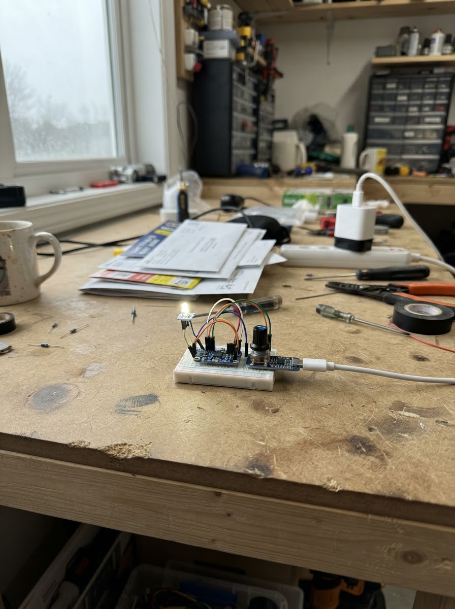
This project builds a high-power LED dimmer controlled by a potentiometer knob. A 1W white LED is driven by the Adafruit TPS61169 constant current boost converter, which accepts PWM signals from an Arduino Uno to smoothly adjust brightness from off to full intensity. The potentiometer on the Arduino's analog input maps directly to the LED driver's PWM pin, creating a responsive dimming interface.
The guide includes a complete wiring diagram showing how to connect the potentiometer to the Arduino, route the PWM output to the LED driver, and properly power the boost converter from a USB-C 5V adapter. Assembly steps cover mounting the LED on a heat sink, configuring the driver for the specific LED, and uploading the firmware that handles knob reading with noise filtering to keep the light steady.
Wiring diagram

Gather all the parts
Assemble it in 7 steps
1. Mount the LED on a heat sink
Screw the 1 W star LED onto a small aluminium heat sink using thermal tape or a thin layer of thermal paste. Keep the two pads marked + and - accessible. The metal heat sink carries away heat that would otherwise damage the LED.
- The pad marked + is the positive LED pad; the other pad is negative.
- Do not run the LED for more than a brief test unless it is fixed to the heat sink.
- The LED and heat sink can become hot enough to burn you, and a 1 W LED can be damaged without a heat sink. Do not look directly into the bright LED.
2. Set the driver for this LED
Use the printed table on the TPS61169 driver board to set its small current-selection switches for 350 mA. This limits the current to a safe level for the 1 W white LED.
- Use a pen tip or small screwdriver to move the tiny switches.
- Read the switch table printed on the actual board; do not guess the switch pattern.
- A setting above 350 mA can overheat and permanently damage the 1 W LED.
3. Connect the driver to the LED
Connect driver L+ to the star LED pad marked +, and connect driver L- to the other star LED pad marked -. These two wires carry the controlled current that lights the LED.
- L+ → LED + (controlled LED power), L- → LED - (controlled LED return).
- Use red wire for L+ and black wire for L- to make the polarity obvious.
- Do not swap the LED wires — reversed polarity prevents it from lighting. Never connect the 1 W LED directly to a Nano pin, Nano 5V, or a breadboard power rail.
4. Wire the brightness knob to the Nano
With the knob shaft facing you and its three legs pointing down, connect one outer leg to Nano 5V, the middle leg to Nano A0, and the other outer leg to Nano GND. The middle leg tells the Nano where the knob is turned.
- Outer leg → 5V (power), middle leg → A0 (brightness signal), other outer leg → GND (ground).
- If clockwise makes the light dimmer, unplug everything and swap only the two outer knob wires.
- Do not connect the Nano 5V wire to the middle knob leg — that can damage the Nano input.
5. Connect the Nano to the LED driver
Connect Nano D9 to the driver PWM pin. Connect Nano GND to the driver GND pin. D9 is the brightness signal, and the GND wire gives that signal a common reference.
- D9 → PWM (brightness signal), Nano GND → driver GND (shared ground).
- Keep this GND link even though the driver uses its own wall adapter.
- Do not connect the driver VCC terminal to the Nano 5V pin; the LED driver is powered by the separate 5 V adapter in the next step.
6. Power the LED driver separately
Connect the dedicated regulated 5 V adapter positive output to the driver VCC terminal and its GND output to the driver GND terminal. Plug this adapter into the wall only after every low-voltage wire has been checked.
- Adapter +5V → driver VCC (driver power), adapter GND → driver GND (ground).
- Use an adapter rated for at least 1 A at 5 V.
- Do not use an unregulated supply or a supply above 5 V — that can damage the LED driver. Make sure no loose L+ or L- wire strands can touch each other.
7. Deploy and test
Turn the knob fully down. Plug the Nano into its own USB cable, then plug in the separate 5 V adapter for the LED driver. Press Deploy in Schematik, then slowly turn the knob up to change the brightness.
- The LED should brighten and dim smoothly as you turn the knob.
- If it stays off, unplug both power sources first, then check the LED + and - wires, the 350 mA driver setting, and the Nano-to-driver GND wire.
- Do not touch the LED or heat sink while testing at high brightness; it can become hot.
Review all connections
1. Connections between "brightness_knob" and "Arduino"
2. Connections between "led_power_adapter" and "Arduino"
3. Connections between "led_driver" and "Arduino"
4. Connections between "white_led_1w" and "Arduino"
Deploy the firmware
#include <Arduino.h>

// High-power LED dimmer for a classic ATmega328P Arduino Nano.
// The knob on A0 controls D9, which is connected to the LED driver's PWM input.

const uint8_t LED_PWM_PIN = 9;
const uint8_t BRIGHTNESS_KNOB_PIN = A0;
const unsigned long KNOB_UPDATE_INTERVAL_MS = 25;
const uint8_t CHANGE_DEADBAND = 2;

uint8_t appliedBrightness = 255;
unsigned long lastKnobUpdateMs = 0;

void setup() {
  pinMode(LED_PWM_PIN, OUTPUT);
  analogWrite(LED_PWM_PIN, 0);  // Start safely with the LED off.
  appliedBrightness = 0;
}

void loop() {
  const unsigned long now = millis();
  if (now - lastKnobUpdateMs < KNOB_UPDATE_INTERVAL_MS) {
    return;
  }
  lastKnobUpdateMs = now;

  const int knobReading = analogRead(BRIGHTNESS_KNOB_PIN);
  const uint8_t requestedBrightness = map(knobReading, 0, 1023, 0, 255);

  // Ignore tiny changes caused by electrical noise so the light stays steady.
  if (abs((int)requestedBrightness - (int)appliedBrightness) > CHANGE_DEADBAND) {
    analogWrite(LED_PWM_PIN, requestedBrightness);
    appliedBrightness = requestedBrightness;
  }
}
Remix this project
Make it yours in one click
Open a full copy of this project in your own Schematik workspace — diagram, code, parts, and assembly steps included. Swap the sensor, add features, or redesign the whole thing with AI. The author's original stays untouched.