Community project
Push-To-Talk AI Assistant
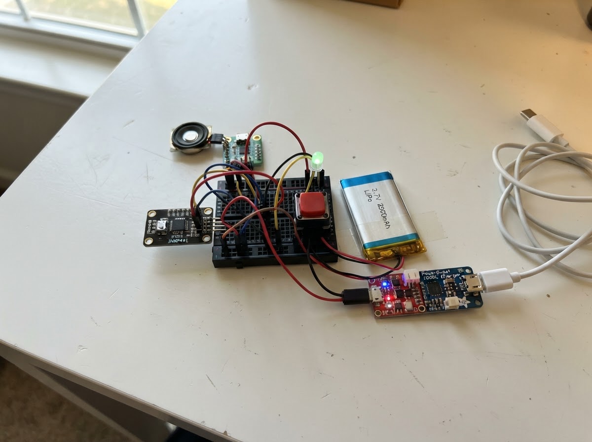
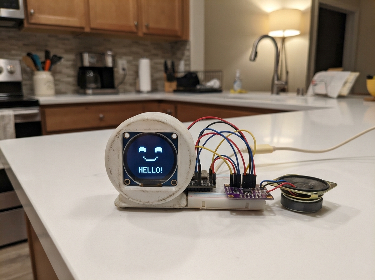
This push-to-talk AI assistant brings voice interaction to embedded projects using an ESP32 microcontroller. Press the button to record audio, send it to OpenAI's API for transcription and processing, and hear the response through a speaker—all powered by a rechargeable lithium battery with integrated charging.
The guide provides a complete wiring diagram, parts list, and firmware code to get the system running. Assembly covers the power delivery chain (charger module and boost converter), I2S microphone input, audio output through the DAC, button control, and RGB status LED. With everything connected and configured, makers can customize the AI prompts and integrate this voice interface into their own projects.
Wiring diagram

Gather all the parts
Assemble it in 6 steps
1. Power chain
Connect the LiPo battery JST plug to the TP4056 charger B+/B- pads. Wire TP4056 OUT+ → PowerBoost BAT, OUT- → PowerBoost GND. PowerBoost 5V → ESP32 VIN, PowerBoost GND → ESP32 GND. To charge, plug USB-C into the TP4056.
- Never reverse battery polarity — the JST connector is polarised, double-check before plugging in.
2. INMP441 microphone
Connect INMP441: VDD → 3.3V, GND → GND, SCK → GPIO32, WS → GPIO25, SD → GPIO33, L/R → GND (selects left-channel mono).
3. PCM5102A DAC + 3.5mm jack
Connect PCM5102A: VCC → 3.3V, GND → GND, BCK → GPIO26, LCK → GPIO27, DIN → GPIO14. Tie FMT and SCK pads to GND on the module. Wire DAC LOUT → jack TIP, ROUT → jack RING, jack SLEEVE → GND. Plug wired headphones into the 3.5mm jack.
- Most PCM5102A breakout boards have solder-bridge pads to tie FMT/SCK/XSMT — bridge them to GND as instructed on the silkscreen.
4. Pushbutton
Connect one leg of the momentary button to GPIO4, the other leg to GND. No external pull-up resistor needed — the ESP32 internal pull-up is enabled in firmware.
5. RGB LED
Connect: GPIO16 → 100Ω resistor (res_r) → LED R pin; GPIO17 → 100Ω (res_g) → LED G; GPIO18 → 100Ω (res_b) → LED B; LED GND (common cathode) → GND.
- Flat side of the LED is the cathode (GND leg).
6. Configure firmware & power on
Before deploying, edit main.cpp and replace YOUR_WIFI_SSID, YOUR_WIFI_PASSWORD, and sk-YOUR_OPENAI_API_KEY with your real credentials. Hit Deploy in Schematik. Once the LED goes off after boot, hold the button for up to 5 seconds to speak, then release — blue = thinking, green = AI speaking.
- Keep your OpenAI API key private — do not share the compiled binary or source.
Review all connections
1. Connections between "battery" and "ESP32"
2. Connections between "charger" and "ESP32"
3. Connections between "boost" and "ESP32"
4. Connections between "mic" and "ESP32"
5. Connections between "dac" and "ESP32"
6. Connections between "jack" and "ESP32"
7. Connections between "button" and "ESP32"
8. Connections between "res_r" and "ESP32"
9. Connections between "res_g" and "ESP32"
10. Connections between "res_b" and "ESP32"
11. Connections between "led" and "ESP32"
Deploy the firmware
#include <Arduino.h>
#include <WiFi.h>
#include <HTTPClient.h>
#include <ArduinoJson.h>
#include <driver/i2s.h>

#define WIFI_SSID "YOUR_WIFI_SSID"
#define WIFI_PASS "YOUR_WIFI_PASSWORD"
#define OPENAI_KEY "sk-YOUR_OPENAI_API_KEY"
#define BTN_PIN 4
#define LED_R 16
#define LED_G 17
#define LED_B 18
#define MIC_SCK 32
#define MIC_WS 25
#define MIC_SD 33
#define DAC_BCK 26
#define DAC_LCK 27
#define DAC_DIN 14
#define SAMPLE_RATE 16000
#define RECORD_SECONDS 5
#define PCM_BYTES (SAMPLE_RATE * 2 * RECORD_SECONDS)


// Forward declarations
void led(bool r,bool g,bool b);
void initMic();
void initDac();
uint8_t* wavFromMic(size_t &wavLen);
String postJson(const char* url,const String &body);
String transcribe(uint8_t* wav,size_t n);
String askAI(const String& q);
void speak(const String& text);

void led(bool r,bool g,bool b){digitalWrite(LED_R,r);digitalWrite(LED_G,g);digitalWrite(LED_B,b);}
void initMic(){
  i2s_config_t c={.mode=(i2s_mode_t)(I2S_MODE_MASTER|I2S_MODE_RX),.sample_rate=SAMPLE_RATE,.bits_per_sample=I2S_BITS_PER_SAMPLE_32BIT,.channel_format=I2S_CHANNEL_FMT_ONLY_LEFT,.communication_format=I2S_COMM_FORMAT_STAND_I2S,.intr_alloc_flags=ESP_INTR_FLAG_LEVEL1,.dma_buf_count=8,.dma_buf_len=512,.use_apll=false,.tx_desc_auto_clear=false,.fixed_mclk=0};
  i2s_pin_config_t p={.bck_io_num=MIC_SCK,.ws_io_num=MIC_WS,.data_out_num=I2S_PIN_NO_CHANGE,.data_in_num=MIC_SD};
  i2s_driver_install(I2S_NUM_0,&c,0,NULL); i2s_set_pin(I2S_NUM_0,&p);
}
void initDac(){
  i2s_config_t c={.mode=(i2s_mode_t)(I2S_MODE_MASTER|I2S_MODE_TX),.sample_rate=24000,.bits_per_sample=I2S_BITS_PER_SAMPLE_16BIT,.channel_format=I2S_CHANNEL_FMT_RIGHT_LEFT,.communication_format=I2S_COMM_FORMAT_STAND_I2S,.intr_alloc_flags=ESP_INTR_FLAG_LEVEL1,.dma_buf_count=8,.dma_buf_len=512,.use_apll=false,.tx_desc_auto_clear=true,.fixed_mclk=0};
  i2s_pin_config_t p={.bck_io_num=DAC_BCK,.ws_io_num=DAC_LCK,.data_out_num=DAC_DIN,.data_in_num=I2S_PIN_NO_CHANGE};
  i2s_driver_install(I2S_NUM_1,&c,0,NULL); i2s_set_pin(I2S_NUM_1,&p);
}
uint8_t* wavFromMic(size_t &wavLen){
  static int16_t pcm[PCM_BYTES/2]; size_t used=0;
  while(used<PCM_BYTES){int32_t raw[128];size_t n=0;i2s_read(I2S_NUM_0,raw,sizeof(raw),&n,portMAX_DELAY);for(size_t i=0;i<n/4&&used<PCM_BYTES;i++) {pcm[used/2]=(int16_t)(raw[i]>>14);used+=2;}}
  wavLen=44+used; uint8_t* w=(uint8_t*)malloc(wavLen); if(!w)return nullptr;
  uint32_t ds=used, cs=36+ds, br=SAMPLE_RATE*2; uint16_t one=1, ba=2, bits=16, ch=1;
  memcpy(w,"RIFF",4);memcpy(w+4,&cs,4);memcpy(w+8,"WAVEfmt ",8);uint32_t fmt=16;memcpy(w+16,&fmt,4);memcpy(w+20,&one,2);memcpy(w+22,&ch,2);uint32_t sr=SAMPLE_RATE;memcpy(w+24,&sr,4);memcpy(w+28,&br,4);memcpy(w+32,&ba,2);memcpy(w+34,&bits,2);memcpy(w+36,"data",4);memcpy(w+40,&ds,4);memcpy(w+44,pcm,used);return w;
}
String postJson(const char* url,const String &body){HTTPClient h;h.begin(url);h.addHeader("Authorization",String("Bearer ")+OPENAI_KEY);h.addHeader("Content-Type","application/json");int rc=h.POST(body);String r=rc==200?h.getString():"";h.end();return r;}
String transcribe(uint8_t* wav,size_t n){
  HTTPClient h;h.begin("https://api.openai.com/v1/audio/transcriptions");h.addHeader("Authorization",String("Bearer ")+OPENAI_KEY);String b="----VoiceButton";String a="--"+b+"\r\nContent-Disposition: form-data; name=\"model\"\r\n\r\nwhisper-1\r\n--"+b+"\r\nContent-Disposition: form-data; name=\"file\"; filename=\"voice.wav\"\r\nContent-Type: audio/wav\r\n\r\n",z="\r\n--"+b+"--\r\n";uint8_t* body=(uint8_t*)malloc(a.length()+n+z.length());if(!body){h.end();return "";}memcpy(body,a.c_str(),a.length());memcpy(body+a.length(),wav,n);memcpy(body+a.length()+n,z.c_str(),z.length());h.addHeader("Content-Type","multipart/form-data; boundary="+b);int rc=h.POST(body,a.length()+n+z.length());free(body);String reply=rc==200?h.getString():"";h.end();JsonDocument d;deserializeJson(d,reply);return d["text"].as<String>();
}
String askAI(const String& q){JsonDocument d;d["model"]="gpt-4o-mini";JsonArray m=d["messages"].to<JsonArray>();JsonObject s=m.add<JsonObject>();s["role"]="system";s["content"]="You are a helpful voice assistant. Keep answers concise and natural for speech.";JsonObject u=m.add<JsonObject>();u["role"]="user";u["content"]=q;d["max_tokens"]=256;String b,r;serializeJson(d,b);r=postJson("https://api.openai.com/v1/chat/completions",b);deserializeJson(d,r);return d["choices"][0]["message"]["content"].as<String>();}
void speak(const String& text){JsonDocument d;d["model"]="tts-1";d["input"]=text;d["voice"]="nova";d["response_format"]="pcm";String b;serializeJson(d,b);HTTPClient h;h.begin("https://api.openai.com/v1/audio/speech");h.addHeader("Authorization",String("Bearer ")+OPENAI_KEY);h.addHeader("Content-Type","application/json");if(h.POST(b)!=200){h.end();return;}led(0,1,0);WiFiClient* s=h.getStreamPtr();uint8_t mono[512],stereo[1024];while(h.connected()||s->available()){int a=s->available();if(a<=0){delay(1);continue;}int n=s->readBytes(mono,min(a,512));int16_t* x=(int16_t*)mono;int16_t* y=(int16_t*)stereo;for(int i=0;i<n/2;i++){y[2*i]=x[i];y[2*i+1]=x[i];}size_t done;i2s_write(I2S_NUM_1,stereo,n*2,&done,portMAX_DELAY);}h.end();}
void setup(){Serial.begin(115200);pinMode(BTN_PIN,INPUT_PULLUP);pinMode(LED_R,OUTPUT);pinMode(LED_G,OUTPUT);pinMode(LED_B,OUTPUT);led(0,0,1);WiFi.begin(WIFI_SSID,WIFI_PASS);while(WiFi.status()!=WL_CONNECTED)delay(300);initMic();initDac();led(0,0,0);Serial.println("Ready — hold button to talk.");}
void loop(){if(digitalRead(BTN_PIN)!=LOW)return;delay(30);if(digitalRead(BTN_PIN)!=LOW)return;led(1,0,0);size_t n;uint8_t* w=wavFromMic(n);if(!w){led(0,0,0);return;}led(0,0,1);String q=transcribe(w,n);free(w);if(q.length()){Serial.println("You: "+q);String r=askAI(q);Serial.println("AI: "+r);if(r.length())speak(r);}led(0,0,0);while(digitalRead(BTN_PIN)==LOW)delay(10);}
Remix this project
Make it yours in one click
Open a full copy of this project in your own Schematik workspace — diagram, code, parts, and assembly steps included. Swap the sensor, add features, or redesign the whole thing with AI. The author's original stays untouched.