Community project
Remote Vehicle Fuel Load Monitor
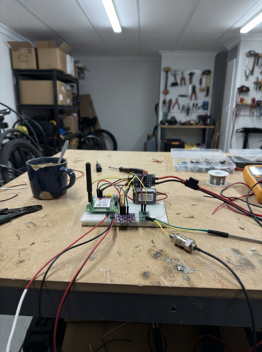
This project builds a remote fuel and load monitoring system for commercial vehicles using cellular LTE connectivity. The ESP32 controller reads diesel fuel level and air-suspension pressure sensors via a 16-bit ADC, then transmits the data over LTE using a SIM7600 modem to a fleet telemetry server. The system converts 4–20 mA sensor signals to digital readings and calculates vehicle load from suspension pressure, enabling real-time fleet visibility.
The guide provides a complete wiring diagram, parts list, and step-by-step assembly instructions for mounting the sealed electronics box in a truck cab or cargo area. Firmware configuration steps show how to set the fleet SIM APN, telemetry server address, and calibration profiles for different vehicle types. Calibration procedures ensure accurate fuel and load readings before field deployment.
Wiring diagram

Gather all the parts
Assemble it in 6 steps
1. Prepare a sealed electronics box
Mount the ESP32, SIM7600, ADS1115, three signal receiver modules, and the 5 V converter inside a dry, vibration-resistant enclosure. Keep the SIM7600 antenna lead outside the metal box or use its supplied external antenna.
- Leave enough slack in every wire so vibration does not pull on a screw terminal.
- Do not mount the cellular or GPS antenna under metal bodywork; metal can prevent it from receiving a signal.
2. Connect the truck power safely
With the truck power switched off, connect the fused harness positive lead to a switched 12–24 V supply and its negative lead to a clean chassis or battery-negative point. Connect the harness ECU output to the converter input, then set and verify the converter output is exactly 5 V before connecting the ESP32 or SIM7600.
- Use a multimeter to check the converter output before plugging in the electronics.
- A truck electrical system can produce damaging voltage spikes. Do not use an unprotected hobby buck converter or bypass the fuse.
3. Wire the controller, modem, and analogue reader
Connect converter 5 V to the SIM7600 VCC and ESP32 VIN/5 V pin, and connect every GND terminal together. Connect SIM7600 TXD to ESP32 GPIO16 (data), SIM7600 RXD to GPIO17 (data), and SIM7600 PWRKEY to GPIO27 (turn-on signal). Connect ADS1115 VDD to ESP32 3V3 (power), ADS1115 GND to GND (ground), SDA to GPIO21 (data), and SCL to GPIO22 (data).
- The ADS1115 is powered from 3.3 V, not 5 V, so its signal wires are safe for the ESP32.
- Do not swap VCC and GND on the SIM7600 or ADS1115 — swapped power can damage them.
4. Fit the air-pressure transmitters
Have a qualified air-suspension technician fit one 0–10 bar, 4–20 mA transmitter to a protected front air-bag pressure point and one to the rear air-bag pressure point. Connect each transmitter V+ to its fused harness output, GND to GND (ground), and OUT to the matching receiver IN+ (signal). Connect front receiver OUT to ADS1115 AIN0 (signal) and rear receiver OUT to AIN1 (signal).
- Label the two sensor cables FRONT and REAR before closing the enclosure.
- Never cut, vent, or open a pressurized air-suspension line yourself. A leak can make the vehicle unsafe to drive.
5. Fit the independent diesel probe
Have a qualified diesel-tank installer fit the diesel-rated 4–20 mA probe using the tank maker's approved sealing method. Connect its V+ to the fused fuel output, GND to GND (ground), and OUT to the fuel receiver IN+ (signal). Connect the receiver OUT to ADS1115 AIN2 (signal). Do not connect this probe to the truck dashboard gauge wiring.
- Keep the fuel-probe cable away from alternator and starter cables to reduce electrical noise.
- Do not drill or open a diesel tank while it contains fuel or vapour. A certified tank installer must make the tank opening and seal it correctly.
6. Calibrate before relying on the readings
First record pressure readings with the truck empty on level ground. Then repeat with known loads to set the correct vehicle profile values in the firmware. Fill and empty the tank in measured steps to confirm the fuel-probe range and tank capacity. The web/mobile service must display the returned sensor-fault flags instead of showing a false fuel or weight number.
- Use certified scale tickets for the known-load checks; air pressure provides an estimate, not a legal trade weight.
- Do not use this prototype as the legal basis for overload enforcement, billing, or safety-critical load decisions until it has been professionally calibrated and approved.
Review all connections
1. Connections between "vehicle_buck_1" and "ESP32"
2. Connections between "sim7600_1" and "ESP32"
3. Connections between "ads1115_1" and "ESP32"
4. Connections between "air_pressure_front_1" and "ESP32"
5. Connections between "air_pressure_rear_1" and "ESP32"
6. Connections between "diesel_level_1" and "ESP32"
7. Connections between "front_loop_receiver_1" and "ESP32"
8. Connections between "rear_loop_receiver_1" and "ESP32"
9. Connections between "fuel_loop_receiver_1" and "ESP32"
10. Connections between "truck_power_harness_1" and "ESP32"
Deploy the firmware
#define TINY_GSM_MODEM_SIM7600
#define TINY_GSM_RX_BUFFER 1024

#include <Arduino.h>
#include <Wire.h>
#include <TinyGsmClient.h>
#include <ArduinoHttpClient.h>
#include <Adafruit_ADS1X15.h>

// These pins match the installed SIM7600 and ADS1115 wiring.
static const int MODEM_RX_PIN = 16;
static const int MODEM_TX_PIN = 17;
static const int MODEM_PWRKEY_PIN = 27;
static const int I2C_SDA_PIN = 21;
static const int I2C_SCL_PIN = 22;

// Set these three values for the fleet SIM and the telemetry server before field use.
static const char APN[] = "SET_FLEET_SIM_APN";
static const char APN_USER[] = "";
static const char APN_PASS[] = "";
static const char TELEMETRY_HOST[] = "telemetry.example.invalid";
static const uint16_t TELEMETRY_PORT = 80;
static const char TELEMETRY_PATH[] = "/api/v1/vehicle-telemetry";
static const char VEHICLE_ID[] = "TRUCK-001";

// The signal receiver modules produce 0.6 V at 4 mA and 3.0 V at 20 mA.
static const float LOOP_MIN_V = 0.60f;
static const float LOOP_MAX_V = 3.00f;
static const float SENSOR_MIN_BAR = 0.0f;
static const float SENSOR_MAX_BAR = 10.0f;
static const float FUEL_TANK_LITRES = 400.0f;  // Change to the actual calibrated tank capacity.

// Calibration profiles: replace coefficients after weighing each vehicle empty and loaded.
struct VehicleProfile {
  const char *name;
  float emptyTonnes;
  float frontTonnesPerBar;
  float rearTonnesPerBar;
};
static const VehicleProfile PROFILES[] = {
  {"rigid_light", 5.0f, 0.18f, 0.42f},
  {"rigid_heavy", 8.5f, 0.24f, 0.62f},
  {"tractor_trailer", 13.0f, 0.30f, 0.85f}
};
static const uint8_t ACTIVE_PROFILE = 2;
static const unsigned long REPORT_INTERVAL_MS = 120000UL;

HardwareSerial modemSerial(2);
TinyGsm modem(modemSerial);
TinyGsmClient cellularClient(modem);
Adafruit_ADS1115 ads;

struct Measurement {
  float volts;
  float percent;
  bool valid;
};

float latitude = 0.0f;
float longitude = 0.0f;
bool gpsValid = false;
unsigned long lastReportMs = 0;

Measurement readLoop(uint8_t channel) {
  int16_t raw = ads.readADC_SingleEnded(channel);
  // GAIN_ONE gives 0.125 mV per count. The ADC is powered from the ESP32 3.3 V rail.
  float volts = raw * 0.000125f;
  bool valid = volts >= (LOOP_MIN_V - 0.12f) && volts <= (LOOP_MAX_V + 0.12f);
  float percent = (volts - LOOP_MIN_V) * 100.0f / (LOOP_MAX_V - LOOP_MIN_V);
  percent = constrain(percent, 0.0f, 100.0f);
  return {volts, percent, valid};
}

void powerModemOn() {
  pinMode(MODEM_PWRKEY_PIN, OUTPUT);
  digitalWrite(MODEM_PWRKEY_PIN, LOW);
  delay(100);
  digitalWrite(MODEM_PWRKEY_PIN, HIGH);
  delay(1200);
  digitalWrite(MODEM_PWRKEY_PIN, LOW);
  delay(5000);
}

bool updateGps() {
  float lat = 0.0f;
  float lon = 0.0f;
  // SIM7600 supplies GNSS through AT commands; its external GNSS antenna must be fitted.
  if (modem.enableGPS() && modem.getGPS(&lat, &lon)) {
    latitude = lat;
    longitude = lon;
    gpsValid = true;
    return true;
  }
  gpsValid = false;
  return false;
}

bool telemetryConfigured() {
  return strcmp(APN, "SET_FLEET_SIM_APN") != 0 &&
         strcmp(TELEMETRY_HOST, "telemetry.example.invalid") != 0;
}

bool postTelemetry(const String &json) {
  if (!telemetryConfigured()) {
    Serial.println("Telemetry not sent: set APN and server host first.");
    return false;
  }
  if (!modem.isNetworkConnected() && !modem.waitForNetwork(60000L)) {
    Serial.println("Cellular network unavailable.");
    return false;
  }
  if (!modem.isGprsConnected() && !modem.gprsConnect(APN, APN_USER, APN_PASS)) {
    Serial.println("Cellular data connection failed.");
    return false;
  }
  HttpClient http(cellularClient, TELEMETRY_HOST, TELEMETRY_PORT);
  http.post(TELEMETRY_PATH, "application/json", json);
  int statusCode = http.responseStatusCode();
  String response = http.responseBody();
  Serial.printf("Telemetry HTTP status: %d\n", statusCode);
  if (response.length() > 0) Serial.println(response);
  http.stop();
  return statusCode >= 200 && statusCode < 300;
}

void reportMeasurements() {
  Measurement front = readLoop(0);
  Measurement rear = readLoop(1);
  Measurement fuel = readLoop(2);
  const VehicleProfile &profile = PROFILES[ACTIVE_PROFILE];

  float frontBar = SENSOR_MIN_BAR + (front.percent / 100.0f) * (SENSOR_MAX_BAR - SENSOR_MIN_BAR);
  float rearBar = SENSOR_MIN_BAR + (rear.percent / 100.0f) * (SENSOR_MAX_BAR - SENSOR_MIN_BAR);
  bool loadValid = front.valid && rear.valid;
  float grossTonnes = profile.emptyTonnes + frontBar * profile.frontTonnesPerBar + rearBar * profile.rearTonnesPerBar;
  float cargoTonnes = max(0.0f, grossTonnes - profile.emptyTonnes);
  float fuelLitres = (fuel.percent / 100.0f) * FUEL_TANK_LITRES;

  updateGps();
  String json = "{\"vehicle_id\":\"" + String(VEHICLE_ID) + "\",";
  json += "\"profile\":\"" + String(profile.name) + "\",";
  json += "\"gps_valid\":" + String(gpsValid ? "true" : "false") + ",";
  json += "\"latitude\":" + String(latitude, 6) + ",\"longitude\":" + String(longitude, 6) + ",";
  json += "\"front_pressure_bar\":" + String(frontBar, 2) + ",\"rear_pressure_bar\":" + String(rearBar, 2) + ",";
  json += "\"fuel_percent\":" + String(fuel.percent, 1) + ",\"fuel_litres\":" + String(fuelLitres, 1) + ",";
  json += "\"front_sensor_ok\":" + String(front.valid ? "true" : "false") + ",";
  json += "\"rear_sensor_ok\":" + String(rear.valid ? "true" : "false") + ",";
  json += "\"fuel_sensor_ok\":" + String(fuel.valid ? "true" : "false") + ",";
  json += "\"load_sensor_ok\":" + String(loadValid ? "true" : "false") + ",";
  json += "\"estimated_gross_tonnes\":" + String(grossTonnes, 2) + ",";
  json += "\"estimated_cargo_tonnes\":" + String(cargoTonnes, 2) + "}";

  Serial.println(json);
  postTelemetry(json);
}

void setup() {
  Serial.begin(115200);
  Wire.begin(I2C_SDA_PIN, I2C_SCL_PIN);
  if (!ads.begin()) {
    Serial.println("ADS1115 not found. Check its power and the two I2C wires.");
    while (true) delay(1000);
  }
  ads.setGain(GAIN_ONE);

  modemSerial.begin(115200, SERIAL_8N1, MODEM_RX_PIN, MODEM_TX_PIN);
  powerModemOn();
  if (!modem.restart()) {
    Serial.println("SIM7600 did not answer. Check its 5 V, ground, antenna, and PWRKEY wire.");
  }
  Serial.println("Truck telemetry node started.");
}

void loop() {
  if (millis() - lastReportMs >= REPORT_INTERVAL_MS || lastReportMs == 0) {
    lastReportMs = millis();
    reportMeasurements();
  }
  delay(50);
}
Remix this project
Make it yours in one click
Open a full copy of this project in your own Schematik workspace — diagram, code, parts, and assembly steps included. Swap the sensor, add features, or redesign the whole thing with AI. The author's original stays untouched.