Community project
ESP32 Quadcopter Controller
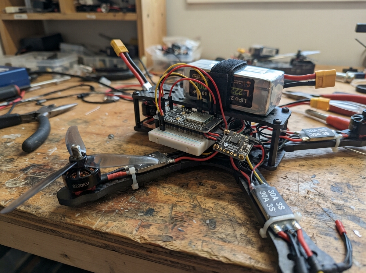
This guide builds a tethered ESP32-based quadcopter controller suitable for initial flight testing and development. The system uses an MPU-6050 inertial measurement unit for attitude sensing, four brushless motors with electronic speed controllers, and a 3S LiPo battery stepped down to logic levels via a buck converter. All components are wired to the ESP32, which runs a stabilization loop and exposes a web interface for arming and throttle control.
Following this guide, you will receive a complete wiring diagram, a detailed parts list with recommended suppliers, the full Arduino firmware with WiFi setup and PID stabilization, and step-by-step assembly instructions. The firmware includes safety features like command timeouts and deliberately limited motor output for safe tethered operation. Before first flight, the guide walks through motor direction verification without propellers attached.
Wiring diagram

Gather all the parts
Assemble it in 6 steps
1. Prepare the frame and remove the propellers
Bolt the four 2200 KV motors to the four arms, naming them front-left, front-right, rear-right, and rear-left when viewed from above. Leave every propeller off for all first power-up and direction tests.
- Mark the front of the frame with tape so the motor names do not get swapped.
- A bare 2200 KV motor can start suddenly; fitting propellers during setup can cause serious cuts or pull the frame from the bench.
2. Join each motor to its own controller
Connect the three wires from motor_fl to M1, M2, and M3 on esc_fl. Repeat the same three-wire connection for each matching front-right, rear-right, and rear-left motor and ESC. If a motor later spins the wrong way, unplug the battery and swap any two of its three motor wires.
- Keep each ESC close to its motor so the three phase wires are short and cannot reach a propeller.
3. Make the low-voltage power supply
Before joining it to the ESP32, use a meter and adjust buck_5v_1 so VOUT is exactly 5.0 V. Connect battery_3s_1 PACK+ to buck_5v_1 VIN (power) and PACK- to buck_5v_1 GND (ground). Connect buck_5v_1 VOUT to the ESP32 5V/VIN pin (power) and its GND to an ESP32 GND pin (ground).
- Set and measure the regulator output with the battery connected but the ESP32 disconnected first.
- Do not use a boost converter here: a fully charged 3S LiPo is 12.6 V, so boosting it cannot make a safe 5 V supply. More than 5 V on the ESP32 5V/VIN pin can damage it.
4. Wire the motion sensor
Connect mpu6050_1 VIN to ESP32 3V3 (power), GND to ESP32 GND (ground), SDA to GPIO21 (data), and SCL to GPIO22 (clock). Mount the small board flat and firmly at the center of the frame with its printed axes aligned to the frame; do not connect its optional INT pin.
- A foam pad can reduce vibration, but the sensor must not wobble or tilt on the pad.
- Do not swap VIN and GND — swapped power can damage the sensor.
5. Wire the four control leads
Connect esc_fl SIGNAL to GPIO25 (signal), esc_fr SIGNAL to GPIO26 (signal), esc_rr SIGNAL to GPIO27 (signal), and esc_rl SIGNAL to GPIO33 (signal). Connect every ESC BAT+ to battery_3s_1 PACK+ (power) and every ESC BAT- to battery_3s_1 PACK- (ground); this shared negative wire is needed so the control signals have a common reference.
- Use a proper high-current distribution board or correctly rated soldered junction for the four battery branches, not thin breadboard jumper wires.
- Never plug four separate ESC 5 V BEC red wires into the ESP32. This design uses the buck converter instead; insulate or remove unused ESC BEC positive leads if your ESC has them.
6. Check directions without propellers
Place the frame on a clear bench, connect the LiPo, join the phone to Wi-Fi network Quad-Setup using password drone-setup, and open 192.168.4.1. Keep throttle at zero, press ARM, then increase it only enough to identify each motor. Press DISARM before touching any wire.
- The controls are intentionally limited to 25% throttle for the first tethered checks.
- Disconnect the LiPo before changing any wire. A LiPo short can heat wires, start a fire, and permanently damage the battery.
Review all connections
1. Connections between "battery_3s_1" and "ESP32"
2. Connections between "buck_5v_1" and "ESP32"
3. Connections between "mpu6050_1" and "ESP32"
4. Connections between "esc_fl" and "ESP32"
5. Connections between "esc_fr" and "ESP32"
6. Connections between "esc_rr" and "ESP32"
7. Connections between "esc_rl" and "ESP32"
Deploy the firmware
#include <Arduino.h>
#include <WiFi.h>
#include <WebServer.h>
#include <Wire.h>
#include <ESP32Servo.h>
#include <math.h>

#define ESC_FL_PIN 25
#define ESC_FR_PIN 26
#define ESC_RR_PIN 27
#define ESC_RL_PIN 33
#define MPU_SDA_PIN 21
#define MPU_SCL_PIN 22

const char *AP_NAME = "Quad-Setup";
const char *AP_PASSWORD = "drone-setup";
const uint8_t MPU_ADDR = 0x68;
const int ESC_STOP_US = 1000;
const int ESC_MAX_US = 1500;       // Deliberately limited for initial tethered tests.
const uint32_t COMMAND_TIMEOUT_MS = 400;
const float MAX_TILT_DEG = 35.0f;
const float P_GAIN = 3.5f;

Servo escFL, escFR, escRR, escRL;
WebServer server(80);

bool armed = false;
float throttleCommand = 0.0f;
float rollCommand = 0.0f;
float pitchCommand = 0.0f;
float yawCommand = 0.0f;
float rollDeg = 0.0f;
float pitchDeg = 0.0f;
uint32_t lastCommandMs = 0;
uint32_t lastImuUs = 0;

const char INDEX_HTML[] PROGMEM = R"HTML(
<!doctype html><html><head><meta name="viewport" content="width=device-width,initial-scale=1">
<style>body{font-family:sans-serif;max-width:420px;margin:20px;background:#151a20;color:#eee}button,input{width:100%;margin:8px 0;font-size:18px}button{padding:12px}#arm{background:#c33;color:white}label{display:block}</style></head><body>
<h2>Quad setup control</h2><p id="status">Connect, keep propellers OFF, then arm.</p>
<button id="arm" onclick="toggleArm()">ARM</button>
<label>Throttle <output id="tv">0</output>%<input id="t" type="range" min="0" max="25" value="0" oninput="send()"></label>
<label>Roll <output id="rv">0</output><input id="r" type="range" min="-15" max="15" value="0" oninput="send()"></label>
<label>Pitch <output id="pv">0</output><input id="p" type="range" min="-15" max="15" value="0" oninput="send()"></label>
<label>Yaw <output id="yv">0</output><input id="y" type="range" min="-15" max="15" value="0" oninput="send()"></label>
<script>
let isArmed=false; const g=id=>document.getElementById(id);
function send(){['t','r','p','y'].forEach(x=>g(x+'v').textContent=g(x).value);fetch(`/set?t=${g('t').value}&r=${g('r').value}&p=${g('p').value}&y=${g('y').value}`).catch(()=>{});}
function toggleArm(){isArmed=!isArmed; if(!isArmed)g('t').value=0; fetch('/arm?state='+(isArmed?1:0)).then(()=>{g('arm').textContent=isArmed?'DISARM':'ARM';g('status').textContent=isArmed?'Armed: keep sending controls.':'Disarmed.';send();});}
setInterval(()=>{if(isArmed)send();},150); send();
</script></body></html>
)HTML";

void writeMotors(int fl, int fr, int rr, int rl) {
  escFL.writeMicroseconds(constrain(fl, ESC_STOP_US, ESC_MAX_US));
  escFR.writeMicroseconds(constrain(fr, ESC_STOP_US, ESC_MAX_US));
  escRR.writeMicroseconds(constrain(rr, ESC_STOP_US, ESC_MAX_US));
  escRL.writeMicroseconds(constrain(rl, ESC_STOP_US, ESC_MAX_US));
}

void stopMotors() { writeMotors(ESC_STOP_US, ESC_STOP_US, ESC_STOP_US, ESC_STOP_US); }

bool readImu() {
  Wire.beginTransmission(MPU_ADDR);
  Wire.write(0x3B);
  if (Wire.endTransmission(false) != 0) return false;
  if (Wire.requestFrom((int)MPU_ADDR, 14) != 14) return false;
  int16_t ax = (Wire.read() << 8) | Wire.read();
  int16_t ay = (Wire.read() << 8) | Wire.read();
  int16_t az = (Wire.read() << 8) | Wire.read();
  Wire.read(); Wire.read();
  int16_t gx = (Wire.read() << 8) | Wire.read();
  int16_t gy = (Wire.read() << 8) | Wire.read();
  Wire.read(); Wire.read();

  uint32_t nowUs = micros();
  float dt = (lastImuUs == 0) ? 0.004f : (nowUs - lastImuUs) / 1000000.0f;
  lastImuUs = nowUs;
  dt = constrain(dt, 0.001f, 0.02f);
  float accRoll = atan2f((float)ay, (float)az) * 180.0f / PI;
  float accPitch = atan2f(-(float)ax, sqrtf((float)ay * ay + (float)az * az)) * 180.0f / PI;
  rollDeg = 0.98f * (rollDeg + (gx / 131.0f) * dt) + 0.02f * accRoll;
  pitchDeg = 0.98f * (pitchDeg + (gy / 131.0f) * dt) + 0.02f * accPitch;
  return true;
}

void setupMpu() {
  Wire.beginTransmission(MPU_ADDR); Wire.write(0x6B); Wire.write(0x00); Wire.endTransmission(true);
  delay(100);
  // Start from the accelerometer tilt while the airframe is still and level.
  readImu();
}

void handleSet() {
  throttleCommand = constrain(server.arg("t").toFloat(), 0.0f, 25.0f);
  rollCommand = constrain(server.arg("r").toFloat(), -15.0f, 15.0f);
  pitchCommand = constrain(server.arg("p").toFloat(), -15.0f, 15.0f);
  yawCommand = constrain(server.arg("y").toFloat(), -15.0f, 15.0f);
  lastCommandMs = millis();
  server.send(200, "text/plain", "ok");
}

void setup() {
  Serial.begin(115200);
  escFL.setPeriodHertz(50); escFR.setPeriodHertz(50); escRR.setPeriodHertz(50); escRL.setPeriodHertz(50);
  escFL.attach(ESC_FL_PIN, 1000, 2000); escFR.attach(ESC_FR_PIN, 1000, 2000);
  escRR.attach(ESC_RR_PIN, 1000, 2000); escRL.attach(ESC_RL_PIN, 1000, 2000);
  stopMotors();
  Wire.begin(MPU_SDA_PIN, MPU_SCL_PIN);
  setupMpu();
  WiFi.mode(WIFI_AP);
  WiFi.softAP(AP_NAME, AP_PASSWORD);
  server.on("/", HTTP_GET, [](){ server.send_P(200, "text/html", INDEX_HTML); });
  server.on("/set", HTTP_GET, handleSet);
  server.on("/arm", HTTP_GET, [](){
    armed = server.arg("state") == "1";
    throttleCommand = 0.0f;
    lastCommandMs = millis();
    if (!armed) stopMotors();
    server.send(200, "text/plain", armed ? "armed" : "disarmed");
  });
  server.begin();
  Serial.println(WiFi.softAPIP());
}

void loop() {
  server.handleClient();
  bool imuOk = readImu();
  if (!armed || !imuOk || (millis() - lastCommandMs > COMMAND_TIMEOUT_MS) || fabsf(rollDeg) > MAX_TILT_DEG || fabsf(pitchDeg) > MAX_TILT_DEG) {
    armed = false;
    throttleCommand = 0.0f;
    stopMotors();
    return;
  }

  float base = ESC_STOP_US + throttleCommand * 20.0f;
  float rollCorrection = (rollCommand - rollDeg) * P_GAIN;
  float pitchCorrection = (pitchCommand - pitchDeg) * P_GAIN;
  float yawMix = yawCommand * 1.5f;
  // X frame: FL and RR rotate one way; FR and RL rotate the other way.
  writeMotors((int)(base + pitchCorrection - rollCorrection - yawMix),
              (int)(base + pitchCorrection + rollCorrection + yawMix),
              (int)(base - pitchCorrection + rollCorrection - yawMix),
              (int)(base - pitchCorrection - rollCorrection + yawMix));
}
Remix this project
Make it yours in one click
Open a full copy of this project in your own Schematik workspace — diagram, code, parts, and assembly steps included. Swap the sensor, add features, or redesign the whole thing with AI. The author's original stays untouched.