Community project
Smart Monitor Audio Hub
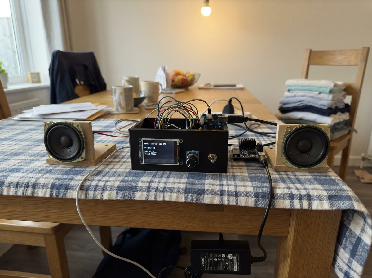
Build a networked audio control hub that bridges your computer's audio output to powered speakers while providing real-time playback information on a bright 2.4-inch display. This project combines an ESP32 microcontroller with a USB audio interface, stereo amplifier, and dual 3-inch speakers to create a compact desktop audio solution with intuitive rotary encoder and button controls.
The guide includes a complete wiring diagram showing how to safely route 12V power through protection circuitry to the amplifier, connect the ST7789 display via SPI, wire the rotary encoder and control buttons, and integrate the PCM2704 USB DAC with the TPA3118D2 amplifier. You'll also get the Arduino firmware that displays track metadata, playback progress, and volume level while communicating with a companion Windows application via serial protocol.
Wiring diagram

Gather all the parts
Assemble it in 6 steps
1. Mantener separadas las dos alimentaciones
No conecte todavía la fuente de 12 V. Alimente el ESP32-S3 DevKitC-1 sólo con su cable USB de datos al PC; ese cable también crea el puerto serie para la pantalla y los controles. Conecte el DAC USB al PC con un segundo cable USB. (Los dos cables USB dan alimentación y comunicación independientes.)
- Use una fuente de 12 V certificada, regulada, de al menos 5 A, con conector compatible con el módulo de protección.
- No conecte 12 V al pin de 3,3 V, 5 V o USB del ESP32: dañaría la placa y la pantalla.
2. Cablear la pantalla
Con el ESP32 desconectado, una VCC de la pantalla a 3V3 (alimentación), GND a GND (tierra), SCL a GPIO12 (reloj), SDA/MOSI a GPIO11 (datos), CS a GPIO10 (selección), DC a GPIO14 (comando/dato), RST a GPIO15 (reinicio) y BL a GPIO16 (luz trasera).
- Use una pantalla ST7789 que acepte lógica de 3,3 V. Si el módulo tiene un regulador pero sus entradas no están especificadas para 3,3 V, no lo use sin conversión de nivel.
- No alimente una pantalla etiquetada sólo para 5 V desde 3V3 sin confirmar su módulo; una pantalla incompatible puede no encender o dañarse.
3. Cablear el mando y los botones
En el encoder, conecte VCC a 3V3 (alimentación), GND a GND (tierra), CLK a GPIO4 (señal), DT a GPIO5 (señal) y SW a GPIO6 (pulsación). En el botón anterior, un terminal a GPIO7 (señal) y el otro a GND (tierra). En el botón siguiente, un terminal a GPIO17 (señal) y el otro a GND (tierra).
- Los botones no requieren resistencias externas: el firmware activa resistencias internas que los mantienen estables.
- Si el encoder gira al revés, intercambie físicamente CLK y DT o invierta la acción en firmware.
- No conecte los pines de señales de estos mandos a 5 V; las entradas del ESP32-S3 son de 3,3 V.
4. Preparar la alimentación protegida del amplificador
Conecte 12V+ de la fuente al IN+ del módulo de protección y GND de la fuente al IN- (entrada). Conecte OUT+ del protector a PVCC del amplificador (12 V protegidos) y OUT- a PGND (retorno de potencia). Conecte el capacitor de 1000 µF entre PVCC, con el terminal +, y PGND, con el terminal −, lo más cerca posible del módulo amplificador.
- Use cables cortos y de sección suficiente para los 12 V y los parlantes; deje los cables de señal de audio alejados de ellos.
- El módulo de protección debe incluir fusible adecuado y MOSFET contra polaridad inversa; mantenga el fusible accesible.
- Respete la banda negativa del capacitor: invertirlo puede calentarlo, dañarlo o hacerlo explotar.
- No energice esta etapa hasta haber revisado dos veces polaridad y ausencia de hilos sueltos.
5. Conectar audio de línea y parlantes
Conecte LINE_L del DAC a LIN del amplificador (audio izquierdo), LINE_R a RIN (audio derecho), y LINE_GND/GND del DAC a AGND del amplificador (retorno de señal). Conecte L+ y L− del amplificador a los terminales + y − del parlante izquierdo. Conecte R+ y R− a los terminales + y − del parlante derecho.
- Use un cable estéreo apantallado corto entre DAC y amplificador; conecte la malla sólo a los terminales de tierra de señal indicados.
- Comience con el control de ganancia del amplificador al mínimo y aumente sólo hasta el nivel de escucha deseado.
- L− y R− son salidas activas BTL, no tierra: no las una entre sí, no las conecte a GND y no use un auricular común en esas salidas; dañaría el amplificador.
- No enchufe ni desenchufe parlantes con los 12 V aplicados.
6. Encender y comprobar en orden
Conecte primero los dos USB al PC y compruebe que la pantalla muestra el estado sin PC. Después conecte la fuente de 12 V al amplificador. Seleccione el DAC USB como salida de audio de Windows y reproduzca a volumen bajo; la aplicación de Windows envía título, estado y volumen al ESP32 por el otro USB.
- Si aparece zumbido, mantenga el DAC, amplificador y cables de señal juntos y lejos de la pantalla/ESP32; si persiste por tierra del PC, añada un aislador de audio de línea de buena calidad entre DAC y amplificador.
- Si escucha distorsión, baje primero el volumen de Windows o la ganancia del amplificador; distorsión sostenida puede dañar parlantes pequeños.
Review all connections
1. Connections between "tft_1" and "ESP32"
2. Connections between "encoder_1" and "ESP32"
3. Connections between "button_previous" and "ESP32"
4. Connections between "button_next" and "ESP32"
5. Connections between "usb_dac_1" and "ESP32"
6. Connections between "psu_12v" and "ESP32"
7. Connections between "power_protection_1" and "ESP32"
8. Connections between "bulk_cap_1" and "ESP32"
9. Connections between "amp_1" and "ESP32"
Deploy the firmware
#include <Arduino.h>
#include <SPI.h>
#include <ArduinoJson.h>
#include <Adafruit_GFX.h>
#include <Adafruit_ST7789.h>


struct PlayerState {
  String title = "Esperando Windows";
  String artist = "Conecte la aplicacion auxiliar";
  String album;
  uint32_t positionMs = 0;
  uint32_t durationMs = 0;
  uint8_t volume = 0;
  bool playing = false;
  bool connected = false;
  bool muted = false;
};


// Forward declarations
void sendCommand(const char *command);
String clipped(const String &text, uint8_t maxChars);
String timeText(uint32_t milliseconds);
void drawStaticUi();
void drawMetadata();
void drawMetadataSafe();
void drawStatus();
void drawProgress();
void refreshUi(bool force);
void parseState(const String &line);
void readSerial();
bool pressedEvent(uint8_t index, int pin);
void readControls();

constexpr int TFT_SCK = 12;
constexpr int TFT_MOSI = 11;
constexpr int TFT_CS = 10;
constexpr int TFT_DC = 14;
constexpr int TFT_RST = 15;
constexpr int TFT_BL = 16;
constexpr int ENC_CLK = 4;
constexpr int ENC_DT = 5;
constexpr int ENC_SW = 6;
constexpr int PREV_BUTTON = 7;
constexpr int NEXT_BUTTON = 17;

Adafruit_ST7789 tft(TFT_CS, TFT_DC, TFT_RST);


PlayerState player;
String inputLine;
uint32_t lastPacketMs = 0;
uint32_t lastUiMs = 0;
uint32_t lastControlMs = 0;
int lastEncoderClk = HIGH;
bool lastButtonLevel[3] = {HIGH, HIGH, HIGH};
bool stableButtonLevel[3] = {HIGH, HIGH, HIGH};
uint32_t lastButtonChange[3] = {0, 0, 0};
uint32_t pressStartMs = 0;
bool encoderPressed = false;
String shownTitle, shownArtist, shownAlbum;
int shownVolume = -1;
bool shownConnected = false, shownPlaying = false, shownMuted = false;
uint32_t shownPosition = UINT32_MAX, shownDuration = UINT32_MAX;

const uint16_t C_BG = 0x0861;
const uint16_t C_PANEL = 0x18C3;
const uint16_t C_TEXT = ST77XX_WHITE;
const uint16_t C_MUTED = 0x8410;
const uint16_t C_ACCENT = 0x2E9F;
const uint16_t C_GREEN = 0x3ECA;
const uint16_t C_RED = 0xF945;

void sendCommand(const char *command) {
  StaticJsonDocument<64> doc;
  doc["cmd"] = command;
  serializeJson(doc, Serial);
  Serial.println();
}

String clipped(const String &text, uint8_t maxChars) {
  if (text.length() <= maxChars) return text;
  return text.substring(0, maxChars - 3) + "...";
}

String timeText(uint32_t milliseconds) {
  uint32_t seconds = milliseconds / 1000;
  char out[12];
  snprintf(out, sizeof(out), "%lu:%02lu", (unsigned long)(seconds / 60), (unsigned long)(seconds % 60));
  return String(out);
}

void drawStaticUi() {
  tft.fillScreen(C_BG);
  tft.fillRoundRect(8, 8, 304, 42, 8, C_PANEL);
  tft.setTextColor(C_TEXT, C_PANEL);
  tft.setTextSize(2);
  tft.setCursor(18, 20);
  tft.print("SMART MONITOR SPEAKER");
  tft.drawRoundRect(8, 62, 304, 116, 8, C_PANEL);
  tft.drawRoundRect(8, 190, 304, 42, 8, C_PANEL);
}

void drawMetadataSafe() {
  // Separate helper keeps the display update localized when text changes.
  tft.fillRect(18, 78, 284, 88, C_PANEL);
  tft.setTextWrap(false);
  tft.setTextColor(C_TEXT, C_PANEL);
  tft.setTextSize(2);
  tft.setCursor(18, 82);
  tft.print(clipped(player.title, 27));
  tft.setTextColor(C_ACCENT, C_PANEL);
  tft.setCursor(18, 111);
  tft.print(clipped(player.artist, 31));
  tft.setTextColor(C_MUTED, C_PANEL);
  tft.setCursor(18, 140);
  tft.print(clipped(player.album, 31));
}

void drawStatus() {
  const bool link = player.connected && (millis() - lastPacketMs < 2500);
  tft.fillCircle(288, 29, 7, link ? C_GREEN : C_RED);
  tft.fillRect(18, 198, 284, 26, C_PANEL);
  tft.setTextSize(2);
  tft.setTextColor(C_TEXT, C_PANEL);
  tft.setCursor(18, 202);
  tft.print(player.playing ? ">" : "||");
  tft.setCursor(55, 202);
  if (player.muted) tft.print("MUTE ");
  tft.print("VOL ");
  tft.print(player.volume);
  tft.print("%");
  tft.setTextColor(link ? C_GREEN : C_RED, C_PANEL);
  tft.setCursor(188, 202);
  tft.print(link ? "PC OK" : "SIN PC");
}

void drawProgress() {
  const uint16_t x = 18, y = 165, w = 284;
  uint32_t duration = player.durationMs;
  uint32_t position = duration ? min(player.positionMs, duration) : 0;
  uint16_t filled = duration ? (uint32_t)w * position / duration : 0;
  tft.fillRoundRect(x, y, w, 8, 4, C_MUTED);
  if (filled) tft.fillRoundRect(x, y, filled, 8, 4, C_ACCENT);
  tft.fillRect(18, 176, 284, 11, C_BG);
  tft.setTextSize(1);
  tft.setTextColor(C_TEXT, C_BG);
  tft.setCursor(18, 178);
  tft.print(timeText(position));
  tft.setCursor(270, 178);
  tft.print(timeText(duration));
}

void refreshUi(bool force = false) {
  const bool link = player.connected && (millis() - lastPacketMs < 2500);
  if (force || player.title != shownTitle || player.artist != shownArtist || player.album != shownAlbum) {
    drawMetadataSafe();
    shownTitle = player.title; shownArtist = player.artist; shownAlbum = player.album;
  }
  if (force || player.positionMs != shownPosition || player.durationMs != shownDuration) {
    drawProgress(); shownPosition = player.positionMs; shownDuration = player.durationMs;
  }
  if (force || player.volume != shownVolume || link != shownConnected || player.playing != shownPlaying || player.muted != shownMuted) {
    drawStatus(); shownVolume = player.volume; shownConnected = link; shownPlaying = player.playing; shownMuted = player.muted;
  }
}

void parseState(const String &line) {
  StaticJsonDocument<768> doc;
  DeserializationError error = deserializeJson(doc, line);
  if (error || String((const char *)(doc["type"] | "")) != "state") return;
  player.connected = doc["connected"] | true;
  player.title = String((const char *)(doc["title"] | "Sin titulo"));
  player.artist = String((const char *)(doc["artist"] | ""));
  player.album = String((const char *)(doc["album"] | ""));
  player.positionMs = doc["position_ms"] | 0;
  player.durationMs = doc["duration_ms"] | 0;
  player.playing = doc["playing"] | false;
  player.volume = constrain(doc["volume"] | 0, 0, 100);
  player.muted = doc["muted"] | false;
  lastPacketMs = millis();
}

void readSerial() {
  while (Serial.available()) {
    char c = (char)Serial.read();
    if (c == '\n') {
      parseState(inputLine);
      inputLine = "";
    } else if (c != '\r' && inputLine.length() < 700) {
      inputLine += c;
    } else if (inputLine.length() >= 700) {
      inputLine = "";
    }
  }
}

bool pressedEvent(uint8_t index, int pin) {
  const bool rawLevel = digitalRead(pin);
  const uint32_t now = millis();
  if (rawLevel != lastButtonLevel[index]) {
    lastButtonLevel[index] = rawLevel;
    lastButtonChange[index] = now;
  }
  if (rawLevel != stableButtonLevel[index] && now - lastButtonChange[index] >= 35) {
    stableButtonLevel[index] = rawLevel;
    return stableButtonLevel[index] == LOW;
  }
  return false;
}

void readControls() {
  int clk = digitalRead(ENC_CLK);
  if (clk != lastEncoderClk && clk == LOW) {
    sendCommand(digitalRead(ENC_DT) == HIGH ? "volume_up" : "volume_down");
  }
  lastEncoderClk = clk;

  bool encoderLevel = digitalRead(ENC_SW);
  if (!encoderPressed && encoderLevel == LOW && millis() - lastButtonChange[0] > 35) {
    encoderPressed = true;
    pressStartMs = millis();
  }
  if (encoderPressed && encoderLevel == HIGH) {
    sendCommand(millis() - pressStartMs >= 700 ? "mute" : "play_pause");
    encoderPressed = false;
    lastButtonChange[0] = millis();
  }
  if (pressedEvent(1, PREV_BUTTON)) sendCommand("previous");
  if (pressedEvent(2, NEXT_BUTTON)) sendCommand("next");
}

void setup() {
  Serial.begin(115200);
  pinMode(TFT_BL, OUTPUT); digitalWrite(TFT_BL, HIGH);
  pinMode(ENC_CLK, INPUT_PULLUP); pinMode(ENC_DT, INPUT_PULLUP); pinMode(ENC_SW, INPUT_PULLUP);
  pinMode(PREV_BUTTON, INPUT_PULLUP); pinMode(NEXT_BUTTON, INPUT_PULLUP);
  lastEncoderClk = digitalRead(ENC_CLK);
  SPI.begin(TFT_SCK, -1, TFT_MOSI, TFT_CS);
  tft.init(240, 320);
  tft.setRotation(1);
  drawStaticUi();
  refreshUi(true);
}

void loop() {
  readSerial();
  readControls();
  uint32_t now = millis();
  if (player.connected && now - lastPacketMs > 2500) player.connected = false;
  if (now - lastUiMs >= 250) {
    lastUiMs = now;
    refreshUi();
  }
}
Remix this project
Make it yours in one click
Open a full copy of this project in your own Schematik workspace — diagram, code, parts, and assembly steps included. Swap the sensor, add features, or redesign the whole thing with AI. The author's original stays untouched.