Community project
Solar Fish Tank Automation
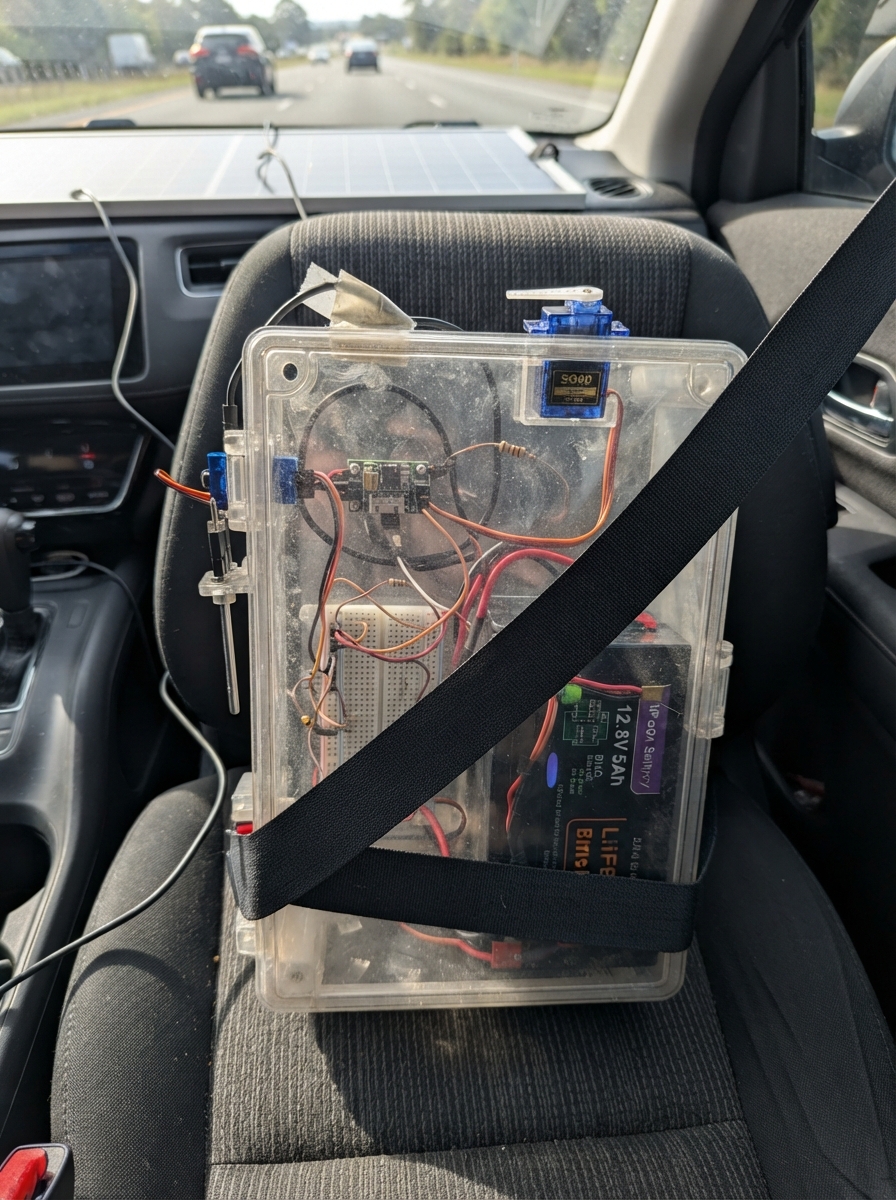
This project automates a fish tank using solar power and an ESP32 microcontroller. It monitors water temperature with a DS18B20 sensor, tracks water clarity using a turbidity sensor, and manages water level with float switches. A servo-driven feeder dispenses food on schedule, while pump control and alarms keep the system running smoothly even during cloudy days thanks to a LiFePO4 battery and Victron MPPT charge controller.
The guide provides a complete wiring diagram, detailed assembly steps, and firmware code to get the system operational. Builders will learn how to integrate solar charging, manage multiple sensors on the ESP32, control actuators safely with fused distribution, and set up a web interface for monitoring and configuration. The modular design supports customization for different tank sizes and automation requirements.
Wiring diagram

Gather all the parts
Assemble it in 11 steps
1. Check the reference ratings before buying or connecting power
Treat this as a report and prototype reference, not a construction-released drawing. Choose aquarium-safe pumps that explicitly accept the battery's full 10–14.6V range: this design assumes M1 is 3W and M2 is 6W, each with measured startup current at most 2A. Confirm battery BMS limits, cold-charge protection, panel voltage and actual connector markings. The fuse values are provisional: compare their trip curves against pump starting current and cable ratings.
- A nominal 12V pump that cannot tolerate 14.6V may be damaged while the battery charges.
- A 20W panel is not guaranteed to maintain continuous filtration: at four equivalent full-sun hours it may supply about 60Wh/day, while the assumed 3W pump plus electronics use about 115Wh/day. Increase solar capacity or provide a properly designed backup before relying on this for livestock.
2. Mount dry electronics and protect the battery cables
Leave the battery disconnected and cover the solar panel. Mount the electronics above splash level in a dry, ventilated enclosure with insulated terminals, strain relief and downward cable loops so drips cannot run inside. Place F1 and F2 within 10cm of battery positive. Use short 18AWG copper power runs with connectors rated at least 5A; use thinner signal wires only for sensors and control. Longer cables require a voltage-drop and ampacity check. Create a negative distribution block connected directly to BAT1 negative.
- Unfused battery cables can overheat or cause a fire if shorted.
- A breadboard is unsuitable for battery and pump current; use secured insulated terminals.
3. Wire the solar charging branch
Connect BAT1 positive to F2 IN (charging cable protection); F2 OUT to SC1 BAT+ (battery charging); BAT1 negative to SC1 BAT− (charging return). Connect PV1 positive to SC1 PV+ (solar power) and PV1 negative to SC1 PV− (solar return). Use the actual engraved controller labels. Leave LOAD terminals unused. Connect the battery before uncovering or connecting the panel. Set the controller for 12V LiFePO4, initially limit charging to 1A, disable equalization and temperature compensation, and use the exact battery maker's charge voltage and duration.
- For this controller, panel open-circuit voltage must exceed battery voltage by 5V to start; an approximately 22V Voc nominal-12V panel is the reference choice.
- The controller's factory settings are not assumed to be correct for the chosen battery.
- Never charge LiFePO4 below its permitted temperature; use a battery with documented low-temperature charge protection or an appropriate charger temperature interlock.
- Swapped PV or battery polarity can damage equipment.
4. Build the fused distribution and set both five-volt supplies
Connect BAT1 positive through F1 to the distribution junction (main load protection). Feed F3, F4 and F5 IN from that junction (branch power). F5 OUT goes to both U2 and U3 VIN+ (regulator input); their VIN− and VOUT− go to the negative block (common ground). With all output loads disconnected, adjust each LM2596 to 5.00V using a meter, then load-test U2 to at least 1A and U3 to at least 1.5A. U2 VOUT+ goes to the ESP32 pin marked 5V or VIN (board power), S2 VCC (sensor power) and Q3 VIN (alarm power). U3 VOUT+ goes only to the servo branch (motor power). Do not join the two regulators' positive outputs.
- A regulator adjusted above 5V can damage the ESP32, servo and sensors.
- Cheap LM2596 modules may not deliver their advertised 3A continuously; check temperature and voltage under load.
- Disconnect U2's 5V wire from the ESP32 before using ordinary powered USB, or use a verified USB power-isolation arrangement; simultaneous supplies can backfeed each other.
5. Connect the temperature and cloudiness sensors
S1 VCC to ESP32 3V3 (power), S1 GND to control ground (return), and S1 DATA to GPIO4 (temperature data). R1 4.7kΩ goes from DATA to 3V3 (data pull-up). Set S2's adapter to A mode. S2 VCC to U2 5V (power), S2 GND to ground (return), and S2 A to R2 P1 (analog signal). R2 10kΩ P2 joins GPIO34, R3 15kΩ P1 and C3 pin 1 (reduced analog voltage); R3 P2 and C3 pin 2 go to ground (divider/filter return). Measure the GPIO34 junction: a 4.5V sensor output should become approximately 2.7V; it must never exceed 3.3V.
- ESP32 inputs are not 5V tolerant; never bypass R2/R3.
- The SEN0189 adapter and probe top are not waterproof: immerse only the allowed optical portion, and verify the manufacturer's long-term immersion limitations.
- Relative turbidity voltage does not measure pH, ammonia, dissolved oxygen or calibrated NTU.
6. Mount and test the three water-level switches
Mount SW1 at the low refill-start height and orient it to CLOSE when wet. Connect SW1 SIGNAL to GPIO32 (level signal) and its other wire to ground (return). Mount SW2 above SW1 and orient it to CLOSE below the high stop height and OPEN when full. Connect SW2 SIGNAL to GPIO33 (level signal) and the other wire to ground (return). Mount independent SW3 above SW2 but below the unsafe overflow height, with its contact CLOSED below that height and OPEN when lifted. Confirm each contact with a meter before connecting. GPIO26 goes through SW3 terminal 1 then terminal 2 to Q2 ON (refill enable). R4 10kΩ goes from Q2 ON, after SW3, to ground (ensures pump stops when the overflow wire opens).
- The internal pull-ups on GPIO32/33 provide the small sensing current; float switches have no separate power input.
- An open HIGH wire stops refilling; an open LOW wire resembles low water and is caught only by high-stop, timeout and independent safeguards.
- Two-wire floats cannot distinguish every stuck contact or broken wire; do not claim complete sensor-failure detection.
- SW3 is independent of software but cannot stop a power switch that has failed short; limit reservoir volume as described below.
7. Wire the pump switches and surge diodes
Set the physical slide switches on Q1, Q2 and Q3 to OFF; otherwise the slide switch can override software or the overflow contact. F3 OUT to Q1 VIN (filter supply), Q1 VOUT to M1 positive (switched pump supply), M1 negative directly to the negative block (motor return), and Q1 GND to that block (control reference). GPIO25 to Q1 ON (filter command), with R5 10kΩ from ON to ground (startup OFF). F4 OUT to Q2 VIN (refill supply), Q2 VOUT to M2 positive (switched supply), and M2 negative directly to the block (motor return); Q2 GND also goes to the block. Fit D1 across M1 and D2 across M2, cathode K/striped end to pump positive (surge clamp) and anode A to pump negative (return). Keep diode leads short and use a properly insulated soldered board for the surface-mount SS54 parts.
- Reversing a flyback diode shorts the supply when the pump is switched on.
- Pump current must not pass through ESP32 ground pins or board traces.
- The Pololu driver rating is thermal and installation-dependent; verify startup current and heating rather than assuming all generic pump modules are interchangeable.
8. Fit the feeder and alarm branches
Servo red VCC to U3 VOUT+ (separate 5V motor supply), servo ground to the negative block (motor return), and servo SIGNAL to GPIO18 (position command). Put C1 positive to servo VCC and C1 negative to servo ground (burst-current support), with C2 across the same terminals (noise suppression). Mechanically attach the servo to a small metering wheel or hopper gate that moves safely between 15° and 100° without reaching a hard stop. GPIO27 to Q3 ON (alarm command), R6 10kΩ from ON to ground (startup OFF), Q3 GND to ground (reference), Q3 VOUT to BZ1 positive (switched 5V), BZ1 negative to ground (return).
- Verify that the chosen SG90 responds reliably to a 3.3V signal; clones may differ. Confirm startup/stall current stays inside the servo regulator's measured capacity.
- Start with an empty hopper and a catch tray; calibrate the physical dose before feeding animals.
- Swapping C1's marked positive and negative leads can rupture the capacitor.
- Never feed motor or buzzer current directly from a GPIO pin.
9. Add the clock backup
U4 VIN to 3V3 (clock power), U4 GND to ground (return), U4 SDA to GPIO21 (clock data), and U4 SCL to GPIO22 (clock signal). Insert BT2 CR1220 in the Adafruit #3013 holder with its positive side as marked (backup power); this corresponds to BAT and ground in the wiring table. Leave SQW, 32K and RST unconnected.
- Do not substitute a generic 5V RTC board with pull-ups to 5V or a coin-cell charging circuit; this design specifically uses the Adafruit board at 3.3V.
- A lithium coin cell must not be recharged.
10. Arrange water hoses and independent containment
Put M1 in the aquarium circulation/filter loop according to its immersion requirements. Put M2 in or beside the clean-water reservoir as specified by its maker. Keep the reservoir below the aquarium and secure the refill outlet above the highest water level with an open air gap so water cannot siphon into or out of the tank. Make the reservoir's usable volume no larger than the tank's measured safe free space above its normal high level, allowing for hose water. Keep all mains chargers and electrical joins away from splashes.
- A check valve alone is not dependable anti-siphon protection.
- The volume limit is essential containment if a switch or MOSFET fails; do not connect this prototype to an unlimited mains-water source.
11. Inspect and perform a supervised freshwater trial
Before use with fish, inspect every terminal and measure 5V, 3.3V and the ADC junction voltage. Use an empty tank or catch tray to test low-start, high-stop, independent overflow-stop, disconnected float wires, and a 30-second unsuccessful refill followed by lockout. Check that the physical slide switches remain OFF and that pump cables and drivers do not heat excessively. Disconnect sensor and control supplies before changing any wiring. The refill system starts disarmed after every power cycle, and timeout lockout is retained.
- Do not leave this prototype unattended with livestock until electrical, water-containment, dose and energy-budget tests pass.
- A 30-second limit is a starting value, not universal: measured pump flow multiplied by that time must fit safely in the tank's available volume.
Review all connections
1. Connections between "PV1" and "ESP32"
2. Connections between "BAT1" and "ESP32"
3. Connections between "F2" and "ESP32"
4. Connections between "SC1" and "ESP32"
5. Connections between "F1" and "ESP32"
6. Connections between "F4" and "ESP32"
7. Connections between "F5" and "ESP32"
8. Connections between "F3" and "ESP32"
9. Connections between "U3" and "ESP32"
10. Connections between "U2" and "ESP32"
11. Connections between "M3" and "ESP32"
12. Connections between "C1" and "ESP32"
13. Connections between "C2" and "ESP32"
14. Connections between "Q1" and "ESP32"
15. Connections between "Q2" and "ESP32"
16. Connections between "M1" and "ESP32"
17. Connections between "M2" and "ESP32"
18. Connections between "SW3" and "ESP32"
19. Connections between "R4" and "ESP32"
20. Connections between "R5" and "ESP32"
21. Connections between "D1" and "ESP32"
22. Connections between "D2" and "ESP32"
23. Connections between "S1" and "ESP32"
24. Connections between "R1" and "ESP32"
25. Connections between "S2" and "ESP32"
26. Connections between "R3" and "ESP32"
27. Connections between "C3" and "ESP32"
28. Connections between "SW1" and "ESP32"
29. Connections between "SW2" and "ESP32"
30. Connections between "U4" and "ESP32"
31. Connections between "BT2" and "ESP32"
32. Connections between "Q3" and "ESP32"
33. Connections between "BZ1" and "ESP32"
34. Connections between "R6" and "ESP32"
35. Connections between "R2" and "ESP32"
Deploy the firmware
#include <Arduino.h>
#include <WiFi.h>
#include <WebServer.h>
#include <Wire.h>
#include <OneWire.h>
#include <DallasTemperature.h>
#include <RTClib.h>
#include <ESP32Servo.h>
#include <Preferences.h>
#include "schematic.h"
constexpr int TEMP_PIN=4,TURB_PIN=34,LOW_PIN=32,HIGH_PIN=33,SDA_PIN=21,SCL_PIN=22,SERVO_PIN=18,FILTER_PIN=25,REFILL_PIN=26,ALARM_PIN=27;
WebServer web(80); Preferences nv; OneWire ow(TEMP_PIN); DallasTemperature ds(&ow); RTC_DS3231 rtc; Servo servo;
bool rtcPresent=false,clockOK=false,tempOK=false,turbFault=false,lowWet=false,highWet=false,cl=false,ch=false,armed=false,locked=false,refilling=false,filter=true,converting=false,fed=false;
uint32_t bootAt,debAt=0,refillAt=0,filterUntil=0,sensorAt=0,convertAt=0,feedAt=0,stageAt=0;
int stage=0,times[2]={480,1080}; uint32_t feedDay[2]={0,0}; float temp=NAN,adc=0,turb=0; String reason;
const char PAGE[] PROGMEM=R"HTML(<!doctype html><html><head><meta name="viewport" content="width=device-width,initial-scale=1"><title>Smart Fish Tank</title><style>body{font:16px Arial;max-width:950px;margin:25px auto;padding:15px}button,input{padding:10px;margin:5px}pre{background:#eee;padding:15px;white-space:pre-wrap}</style></head><body><h1>SMART FISH TANK AUTOMATION SYSTEM — SOLAR-POWERED ESP32</h1><p><a href="/schematic.svg" target="_blank">Engineering schematic — SVG / print landscape</a></p><p>REFERENCE PROTOTYPE: exact pump startup current, battery settings, fuses and energy budget need bench verification.</p><pre id="s">Loading...</pre><button onclick="cmd('/feed')">Feed once</button><button onclick="cmd('/filter?on=0')">Filter OFF for 5 minutes</button><button onclick="cmd('/filter?on=1')">Filter ON</button><h3>Automatic refill</h3><p>30-second maximum runtime. Timeout and contradictory floats lock out further filling, including after restart. Inspect and repair before resetting. Arming is required after each restart.</p><button onclick="cmd('/arm')">Arm after inspection</button><button onclick="cmd('/stop')">Stop / disarm</button><button onclick="cmd('/reset')">Reset fault after repair</button><h3>Two daily feeding times</h3><input id="a" type="time" value="08:00"><input id="b" type="time" value="18:00"><button onclick="cmd('/schedule?a='+document.getElementById('a').value+'&b='+document.getElementById('b').value)">Save schedule</button><button onclick="clock()">Set clock from browser</button><p id="m"></p><p>Clock and feeding continue without internet; an invalid RTC disables scheduled feeds. Manual feeding has a 60-second cooldown. Temperature alert band 20–30°C is an example: adjust for the species.</p><p>LOW float closes when wet. HIGH float opens when full. Independent overflow float opens the refill driver's ON wire. Status shows pump COMMANDS, not measured flow. Two-wire floats cannot identify every wiring fault.</p><p>Turbidity is relative optical voltage, NOT calibrated NTU or proof of safe water. No pH, ammonia or oxygen measurement. Keep the SEN0189 probe top and adapter dry.</p><script>async function cmd(u){let r=await fetch(u,{method:'POST'});document.getElementById('m').innerText=await r.text();poll()}function clock(){let d=new Date();cmd('/clock?y='+d.getFullYear()+'&mo='+(d.getMonth()+1)+'&d='+d.getDate()+'&h='+d.getHours()+'&mi='+d.getMinutes()+'&s='+d.getSeconds())}async function poll(){try{let r=await fetch('/status');let v=await r.json();document.getElementById('s').innerText='Temperature: '+(v.temp===null?'FAULT / unavailable':v.temp+' °C')+'\nTurbidity voltage: '+v.turb+' V (relative)'+'\nADC: '+v.adc+' V\nLOW: '+(v.low?'wet':'dry / open')+'\nHIGH: '+(v.high?'full / open':'below high / closed')+'\nFilter command: '+(v.filter?'ON':'OFF')+'\nRefill command: '+(v.refill?'ON':'OFF')+'\nRefill armed: '+v.armed+'; lockout: '+v.locked+'\nClock: '+v.clock+'\nFeeding schedule: '+v.schedule+'\nAlerts: '+v.alerts}catch(e){document.getElementById('s').innerText='Wi-Fi lost. Local controls continue.'}}setInterval(poll,2000);poll();</script></body></html>)HTML";
bool auth(){if(web.authenticate("admin","TankControl-2026"))return true;web.requestAuthentication();return false;}
void reply(int code,const String &s){web.send(code,"text/plain",s);}
void stop(){refilling=false;digitalWrite(REFILL_PIN,LOW);}
void trip(const String &s){stop();armed=false;reason=s;if(!locked){locked=true;nv.putBool("locked",true);nv.putString("reason",s);}}
String hhmm(int m){char b[8];snprintf(b,sizeof(b),"%02d:%02d",m/60,m%60);return b;}
bool rtcValid(){if(!rtcPresent)return false;DateTime n=rtc.now();return !rtc.lostPower()&&n.year()>=2026&&n.year()<=2099;}
String alerts(){String s;if(locked)s+="REFILL LOCKOUT: "+reason+"; ";if(!armed)s+="Refill disarmed; ";if(!tempOK)s+="Temperature fault; ";else if(temp<20||temp>30)s+="Temperature outside example band; ";if(turbFault)s+="Turbidity near rail: inspect sensor/wiring; ";if(!clockOK)s+="RTC invalid: schedule disabled; ";if(!filter)s+="Filter temporarily OFF; ";return s.length()?s:"None; flow and overflow contact not monitored";}
void safety(uint32_t now){bool l=digitalRead(LOW_PIN)==LOW,h=digitalRead(HIGH_PIN)==HIGH;if(l!=cl||h!=ch){cl=l;ch=h;debAt=now;}if(now-debAt>=100){lowWet=cl;highWet=ch;}if(refilling&&h)stop();if(now-bootAt<1500)return;if(highWet&&!lowWet){trip("Contradictory LOW dry and HIGH full");return;}if(refilling&&now-refillAt>=30000){trip("30s timeout: inspect floats, reservoir and pump");return;}if(armed&&!locked&&!refilling&&!lowWet&&!highWet&&!h){refilling=true;refillAt=now;digitalWrite(REFILL_PIN,HIGH);}if(!armed||locked)stop();if(filterUntil&&(int32_t)(now-filterUntil)>=0){filterUntil=0;filter=true;digitalWrite(FILTER_PIN,HIGH);}}
bool feed(){uint32_t now=millis();if(stage||(fed&&now-feedAt<60000))return false;servo.attach(SERVO_PIN,500,2400);servo.write(15);stage=1;stageAt=feedAt=now;fed=true;return true;}
void feeder(uint32_t now){if(stage==1&&now-stageAt>=400){servo.write(100);stage=2;stageAt=now;}else if(stage==2&&now-stageAt>=600){servo.write(15);stage=3;stageAt=now;}else if(stage==3&&now-stageAt>=600){servo.detach();stage=0;}}
void sensors(uint32_t now){if(now-sensorAt>=2000){sensorAt=now;uint32_t sum=0;for(int i=0;i<16;i++)sum+=analogReadMilliVolts(TURB_PIN);adc=sum/16000.0f;turb=adc/0.6f;turbFault=adc<0.03f||adc>3.05f;clockOK=rtcValid();if(!converting){ds.requestTemperatures();converting=true;convertAt=now;}}if(converting&&now-convertAt>=400){temp=ds.getTempCByIndex(0);tempOK=temp!=DEVICE_DISCONNECTED_C&&temp>=-10&&temp<=60&&temp!=85;converting=false;}if(clockOK){DateTime n=rtc.now();uint32_t day=n.year()*10000UL+n.month()*100UL+n.day();int m=n.hour()*60+n.minute();for(int i=0;i<2;i++)if(m==times[i]&&feedDay[i]!=day){feedDay[i]=day;nv.putUInt(i?"day1":"day0",day);feed();}}}
bool parseTime(String s,int &m){if(s.length()!=5||s[2]!=':'||!isDigit(s[0])||!isDigit(s[1])||!isDigit(s[3])||!isDigit(s[4]))return false;int h=s.substring(0,2).toInt(),min=s.substring(3).toInt();if(h>23||min>59)return false;m=h*60+min;return true;}
void setup(){Serial.begin(115200);bootAt=millis();digitalWrite(REFILL_PIN,LOW);pinMode(REFILL_PIN,OUTPUT);digitalWrite(ALARM_PIN,LOW);pinMode(ALARM_PIN,OUTPUT);digitalWrite(FILTER_PIN,LOW);pinMode(FILTER_PIN,OUTPUT);pinMode(LOW_PIN,INPUT_PULLUP);pinMode(HIGH_PIN,INPUT_PULLUP);pinMode(TURB_PIN,INPUT);analogReadResolution(12);analogSetPinAttenuation(TURB_PIN,ADC_11db);cl=digitalRead(LOW_PIN)==LOW;ch=digitalRead(HIGH_PIN)==HIGH;debAt=millis();nv.begin("tank",false);locked=nv.getBool("locked",false);reason=nv.getString("reason","");for(int i=0;i<2;i++){times[i]=nv.getInt(i?"time1":"time0",i?1080:480);if(times[i]<0||times[i]>1439)times[i]=i?1080:480;feedDay[i]=nv.getUInt(i?"day1":"day0",0);}Wire.begin(SDA_PIN,SCL_PIN);Wire.setTimeOut(50);rtcPresent=rtc.begin();clockOK=rtcValid();ds.begin();ds.setResolution(11);ds.setWaitForConversion(false);servo.setPeriodHertz(50);digitalWrite(FILTER_PIN,HIGH);WiFi.mode(WIFI_AP);WiFi.softAP("FishTank-Solar","TankSolar-2026");
web.on("/",HTTP_GET,[](){if(auth())web.send_P(200,"text/html",PAGE);});web.on("/schematic.svg",HTTP_GET,[](){if(auth())web.send_P(200,"image/svg+xml",SCHEMATIC);});
web.on("/status",HTTP_GET,[](){if(!auth())return;String clock="INVALID";if(clockOK){DateTime n=rtc.now();char b[25];snprintf(b,sizeof(b),"%04u-%02u-%02u %02u:%02u:%02u",n.year(),n.month(),n.day(),n.hour(),n.minute(),n.second());clock=b;}String j="{\"temp\":"+(tempOK?String(temp,2):String("null"))+",\"turb\":"+String(turb,3)+",\"adc\":"+String(adc,3)+",\"low\":"+String(lowWet?"true":"false")+",\"high\":"+String(highWet?"true":"false")+",\"filter\":"+String(filter?"true":"false")+",\"refill\":"+String(refilling?"true":"false")+",\"armed\":"+String(armed?"true":"false")+",\"locked\":"+String(locked?"true":"false")+",\"clock\":\""+clock+"\",\"schedule\":\""+hhmm(times[0])+" / "+hhmm(times[1])+"\",\"alerts\":\""+alerts()+"\"}";web.send(200,"application/json",j);});
web.on("/feed",HTTP_POST,[](){if(auth()){bool ok=feed();reply(ok?200:409,ok?"One metered feed cycle started":"Busy or 60-second feed cooldown");}});
web.on("/filter",HTTP_POST,[](){if(!auth())return;filter=web.arg("on")!="0";filterUntil=filter?0:millis()+300000;digitalWrite(FILTER_PIN,filter?HIGH:LOW);reply(200,filter?"Filter ON":"Filter OFF; resumes in 5 minutes");});
web.on("/arm",HTTP_POST,[](){if(!auth())return;if(locked||millis()-bootAt<1500||(highWet&&!lowWet)){reply(409,"Cannot arm: inspect / repair / reset first");return;}armed=true;reply(200,"Refill armed. Verify independent overflow and reservoir capacity.");});
web.on("/stop",HTTP_POST,[](){if(!auth())return;armed=false;stop();reply(200,"Refill stopped and disarmed");});
web.on("/reset",HTTP_POST,[](){if(!auth())return;armed=false;stop();if(highWet&&!lowWet){reply(409,"Float contradiction persists");return;}locked=false;reason="";nv.putBool("locked",false);nv.putString("reason","");reply(200,"Fault cleared; still disarmed. Test after repair before arming.");});
web.on("/schedule",HTTP_POST,[](){if(!auth())return;int a,b;if(!parseTime(web.arg("a"),a)||!parseTime(web.arg("b"),b)||a==b||abs(a-b)<2){reply(400,"Enter two HH:MM times at least two minutes apart");return;}times[0]=a;times[1]=b;nv.putInt("time0",a);nv.putInt("time1",b);reply(200,"Schedule saved in tank local time");});
web.on("/clock",HTTP_POST,[](){if(!auth())return;if(!rtcPresent){reply(409,"RTC not found: check power and I2C");return;}int y=web.arg("y").toInt(),m=web.arg("mo").toInt(),d=web.arg("d").toInt(),h=web.arg("h").toInt(),mi=web.arg("mi").toInt(),s=web.arg("s").toInt();int days[]={31,28,31,30,31,30,31,31,30,31,30,31};if(y%4==0)days[1]=29;if(y<2026||y>2099||m<1||m>12||d<1||d>31||h<0||h>23||mi<0||mi>59||s<0||s>59){reply(400,"Invalid date/time");return;}if(d>days[m-1]){reply(400,"Invalid calendar date");return;}rtc.adjust(DateTime(y,m,d,h,mi,s));clockOK=rtcValid();reply(200,"RTC set; offline schedule enabled");});web.begin();Serial.println("FishTank-Solar: http://192.168.4.1 / admin / TankControl-2026");Serial.println("Refill disarmed at boot. Status = commands, not flow.");}
void loop(){uint32_t now=millis();safety(now);feeder(now);sensors(now);bool alarm=locked||!tempOK||turbFault||!clockOK||(tempOK&&(temp<20||temp>30));digitalWrite(ALARM_PIN,alarm&&((now/500)%2)?HIGH:LOW);web.handleClient();safety(millis());delay(1);}
Remix this project
Make it yours in one click
Open a full copy of this project in your own Schematik workspace — diagram, code, parts, and assembly steps included. Swap the sensor, add features, or redesign the whole thing with AI. The author's original stays untouched.