Community project
Soldering Stand Fume Extractor
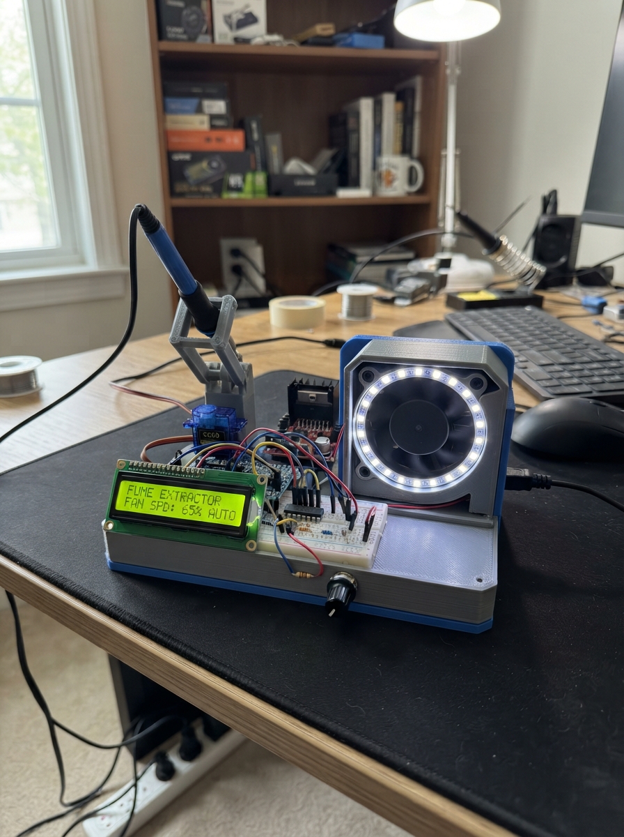
This soldering stand fume extractor keeps your workspace clean and safe during electronics projects. It combines a 12V brushed DC blower fan controlled through an Arduino Uno, dual servo-driven helper arms for holding the iron and sponge, a 24-LED ring for status indication, and an LCD display showing the current state.
This guide provides a complete wiring diagram, detailed parts list, Arduino firmware, and step-by-step assembly instructions. You'll learn how to wire the motor driver for fan speed control, integrate the LCD display, calibrate the servo helpers, and safely configure the dual-voltage power system using a buck converter to step down 12V to 5V for the microcontroller.
Wiring diagram

Gather all the parts
Assemble it in 6 steps
1. Set the 5V converter before connecting the Uno
With the 12V adapter unplugged, turn the LM2596 adjustment screw fully counter-clockwise. Connect the adapter to LM2596 VIN+ and VIN-, plug in the adapter, and measure VOUT+ to VOUT- with a meter. Turn the screw slowly until it reads 5.0V, then unplug the adapter. This creates the safe supply for the Uno, LCD, LED ring, and servos.
- Mark the measured 5V output wire red and its ground wire black.
- Do not connect the converter to the Uno until it measures 5.0V — a higher voltage can damage the Uno and every 5V part.
2. Make the 12V and 5V power connections
Connect adapter +12V to LM2596 VIN+ and L298N VS (motor supply). Connect adapter GND to LM2596 VIN- and L298N GND. Connect LM2596 VOUT+ to Uno 5V, L298N 5V, LCD VCC, both servo red wires, and LED ring 5V. Connect LM2596 VOUT- to all ground points. Remove the L298N 5V-EN jumper and leave its ENA jumper fitted.
- Use a terminal block or power distribution strip for the many 5V and ground wires.
- Never connect 12V to the Uno 5V pin, LCD, LED ring, or servos — it will damage them.
- Every ground must be connected together or the Uno cannot control the other parts reliably.
3. Wire the fume extractor fan through the L298N
Connect the blower wires to L298N OUT1 and OUT2 (motor power). Connect L298N IN1 to Uno D5 (fan control) and IN2 to Uno D6 (fan control). The L298N receives 12V at VS and 5V at its logic pin from the power connections.
- Mount the blower so it pulls smoke through a filter and sends it away from your face.
- Unplug the adapter before swapping fan wires; if airflow is backwards, swap only the two wires at OUT1 and OUT2.
4. Wire the LCD directly to the Uno
Connect LCD GND to GND (ground), VCC to 5V (power), and RW to GND (write-only control). Connect the 10k potentiometer outer legs to 5V and GND, then its middle leg to LCD VO (contrast control). Connect LCD RS to Uno D9 (control), EN to D12 (control), D4 to D13 (data), D5 to A0 (data), D6 to A1 (data), and D7 to A2 (data). Connect 5V through the 220 ohm resistor to LCD LED+ (backlight power), then LCD LED- to GND (ground).
- The LCD uses direct wires now; no shift register is used. Turn the contrast knob slowly after powering up until letters appear.
- Make sure LCD VCC and GND are not swapped — swapped power can damage the display.
5. Add the button, LED ring, and servo helpers
Connect Uno D7 through the 330 ohm resistor to the LED ring DIN pad (data). Connect the 1000 µF capacitor across the ring 5V and GND pads: its long positive lead goes to 5V and striped negative lead to GND. Connect the button between Uno D8 and GND (button signal). Connect the iron-holder servo signal wire to D10 and the sponge-cover servo signal wire to D11 (servo control); both red wires go to 5V and brown or black wires go to GND.
- Use the LED ring pad marked DIN, not DOUT. The button has no positive or negative side.
- Make sure the capacitor striped lead goes to ground — reversing it can overheat or burst it.
- Do not force servo arms by hand while powered; unplug power before repositioning them.
6. Mount and test the stand safely
Mount the blower, filter, iron cradle, sponge cover, button, and servos where moving arms cannot touch the hot iron. With power applied, the display starts at SOLDERING STAND, the ring is orange, the fan is off, and the helpers are parked. Press the button once to run the L298N-controlled fan, turn the ring green, and move both servo helpers out.
- If a servo arm reaches a hard stop, disconnect power and adjust its horn position before using the stand.
- Never solder directly above the Uno, LCD, LED ring, servos, or fan housing — heat and flux can damage them.
Review all connections
1. Connections between "supply_5v" and "Arduino"
2. Connections between "buck_5v" and "Arduino"
3. Connections between "fan_driver" and "Arduino"
4. Connections between "lcd_16x2" and "Arduino"
5. Connections between "contrast_pot" and "Arduino"
6. Connections between "lcd_backlight_resistor" and "Arduino"
7. Connections between "status_ring" and "Arduino"
8. Connections between "ws2812_data_resistor" and "Arduino"
9. Connections between "servo_iron" and "Arduino"
10. Connections between "servo_sponge" and "Arduino"
11. Connections between "stand_button" and "Arduino"
12. Connections between "ring_capacitor" and "Arduino"
Deploy the firmware
#include <Arduino.h>
#include <Adafruit_NeoPixel.h>
#include <LiquidCrystal.h>
#include <Servo.h>


// Forward declarations
void setRingColor(uint8_t red, uint8_t green, uint8_t blue);
void showState();
void applyState();

const uint8_t LCD_RS_PIN = 9;
const uint8_t LCD_ENABLE_PIN = 12;
const uint8_t LCD_D4_PIN = 13;
const uint8_t LCD_D5_PIN = A0;
const uint8_t LCD_D6_PIN = A1;
const uint8_t LCD_D7_PIN = A2;
const uint8_t FAN_IN1_PIN = 5;
const uint8_t FAN_IN2_PIN = 6;
const uint8_t RING_PIN = 7;
const uint8_t BUTTON_PIN = 8;
const uint8_t IRON_SERVO_PIN = 10;
const uint8_t SPONGE_SERVO_PIN = 11;

const uint8_t LED_COUNT = 24;
const unsigned long DEBOUNCE_MS = 35;

LiquidCrystal lcd(LCD_RS_PIN, LCD_ENABLE_PIN, LCD_D4_PIN, LCD_D5_PIN,
                  LCD_D6_PIN, LCD_D7_PIN);
Adafruit_NeoPixel ring(LED_COUNT, RING_PIN, NEO_GRB + NEO_KHZ800);
Servo ironServo;
Servo spongeServo;

bool extractorOn = false;
bool lastButtonReading = HIGH;
bool stableButtonState = HIGH;
unsigned long lastButtonChangeMs = 0;

void setRingColor(uint8_t red, uint8_t green, uint8_t blue) {
  const uint32_t color = ring.Color(red, green, blue);
  for (uint8_t i = 0; i < LED_COUNT; i++) {
    ring.setPixelColor(i, color);
  }
  ring.show();
}

void showState() {
  lcd.setCursor(0, 0);
  if (extractorOn) {
    lcd.print(F("FUME EXTRACTOR  "));
    lcd.setCursor(0, 1);
    lcd.print(F("ON HELPERS OUT  "));
  } else {
    lcd.print(F("SOLDERING STAND "));
    lcd.setCursor(0, 1);
    lcd.print(F("OFF HELPERS PARK"));
  }
}

void applyState() {
  if (extractorOn) {
    digitalWrite(FAN_IN1_PIN, HIGH);
    digitalWrite(FAN_IN2_PIN, LOW);
    ironServo.write(105);  // Set these angles to suit the finished mechanics.
    spongeServo.write(75);
    setRingColor(0, 80, 0);
  } else {
    digitalWrite(FAN_IN1_PIN, LOW);
    digitalWrite(FAN_IN2_PIN, LOW);
    ironServo.write(20);
    spongeServo.write(10);
    setRingColor(80, 20, 0);
  }
  showState();
}

void setup() {
  pinMode(FAN_IN1_PIN, OUTPUT);
  pinMode(FAN_IN2_PIN, OUTPUT);
  pinMode(BUTTON_PIN, INPUT_PULLUP);
  digitalWrite(FAN_IN1_PIN, LOW);
  digitalWrite(FAN_IN2_PIN, LOW);

  lcd.begin(16, 2);
  ring.begin();
  ring.setBrightness(32);  // Limits current drawn by the 24 LEDs.
  ring.show();

  ironServo.attach(IRON_SERVO_PIN);
  spongeServo.attach(SPONGE_SERVO_PIN);
  applyState();
}

void loop() {
  const bool reading = digitalRead(BUTTON_PIN);
  if (reading != lastButtonReading) {
    lastButtonChangeMs = millis();
    lastButtonReading = reading;
  }

  if ((millis() - lastButtonChangeMs >= DEBOUNCE_MS) &&
      (reading != stableButtonState)) {
    stableButtonState = reading;
    if (stableButtonState == LOW) {
      extractorOn = !extractorOn;
      applyState();
    }
  }
}
Remix this project
Make it yours in one click
Open a full copy of this project in your own Schematik workspace — diagram, code, parts, and assembly steps included. Swap the sensor, add features, or redesign the whole thing with AI. The author's original stays untouched.