Community project
Joystick-Controlled Relay Switches
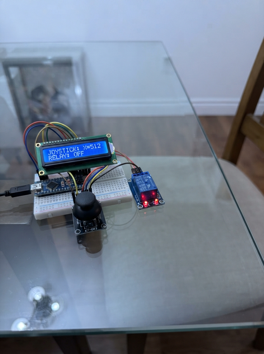
This project builds a two-channel relay controller using a joystick to switch mains-powered appliances on and off. The KY-023 joystick module provides directional input to select between two relay channels, while an LCD1602 display shows the current state of each relay in real time.
The guide includes a complete wiring diagram, parts list, and Arduino firmware with debouncing and relay-state management. Assembly steps keep high-voltage terminals safely disconnected until testing is complete, and the firmware handles the active-LOW relay logic common to most 5V relay boards. Builders will learn relay switching fundamentals and gain a reusable controller template for home automation projects.
Wiring diagram

Gather all the parts
Assemble it in 7 steps
1. Keep the 220 V terminals disconnected while building
Leave the relay board screw terminals labelled COM, NO, and NC empty while connecting the Arduino, joystick, and screen. Put the relay board on a non-metal surface and keep its screw-terminal side away from loose jumper wires.
- You can safely test the controls first by listening for each relay click.
- Those screw terminals can carry dangerous 220 V electricity. Do not touch or wire them while anything is connected to wall power.
2. Wire the joystick
Connect joystick_1 VCC to Uno 5V (power), joystick_1 GND to Uno GND (ground), joystick_1 VRx to A0 (spare position signal), joystick_1 VRy to A1 (selection signal), and joystick_1 SW to D2 (press signal).
- The pin labels are normally printed on the back of the joystick board.
- Make sure VCC and GND are not swapped — swapped power can damage the joystick board.
3. Wire the relay board's low-voltage header
Connect relay_2ch_1 VCC to Uno 5V (power), relay_2ch_1 GND to Uno GND (ground), relay_2ch_1 IN1 to D7 (relay 1 control signal), and relay_2ch_1 IN2 to D8 (relay 2 control signal).
- Keep these small header wires well away from the relay screw terminals.
- Do not power an appliance from the Uno 5V pin. The Uno only controls the relay board; appliance power belongs on the relay screw terminals.
4. Wire the LCD power and contrast pins
With the LCD pins numbered 1 to 16 from left to right when you face the display and its pins point downward, connect lcd1602_1 VSS/pin 1 to Uno GND (ground), VDD/pin 2 to Uno 5V (power), VO/pin 3 to Uno GND (fixed text contrast), R/W/pin 5 to Uno GND (write-only setting), LED_A/pin 15 to Uno 5V (blue backlight power), and LED_K/pin 16 to Uno GND (blue backlight ground).
- If you see the blue glow but no letters, check the pin order first; the screen pin labels are usually printed on its circuit board.
- Make sure VDD and VSS are not swapped — swapped power can damage the screen.
5. Wire the LCD text-control pins
Connect lcd1602_1 RS/pin 4 to D3 (text or command signal), E/pin 6 to D4 (send signal), DB4/pin 11 to D5 (text data), DB5/pin 12 to D6 (text data), DB6/pin 13 to D9 (text data), and DB7/pin 14 to D10 (text data). Leave DB0 through DB3, pins 7 through 10, unconnected because this project uses the screen's four-wire mode.
- Count slowly from pin 1: the LCD has 16 closely-spaced pins, so one shifted wire prevents the text from appearing.
- Unplug USB before moving any wire. A misplaced wire can stop the screen or relays from working.
6. Test the controller before connecting an appliance
Plug the Uno into USB. The screen should say which relay is selected and show R1 and R2 as OFF. Push the joystick up for relay 1 or down for relay 2, then press it once to switch that relay on or off; the screen changes and the selected relay clicks.
- If the screen lights but shows no letters, recheck its pin 3 VO connection to GND and the six text-control wires.
- Do not rely on software alone as a safety switch for a dangerous appliance; unplug power before moving wires.
7. Connect a mains appliance only if qualified
After the low-voltage controller works, unplug all power. For each appliance, route only its live wire through that relay channel's COM and NO screw terminals so it is normally off. Keep neutral and protective earth continuous according to local electrical rules, and place all mains wiring in a closed insulated enclosure.
- If you are not trained for mains wiring, have a qualified electrician make or inspect this connection.
- 220 V can cause fatal electric shock or fire. Never work on live wiring, never leave exposed mains terminals accessible, and do not exceed the relay board's marked voltage and current rating.
Review all connections
1. Connections between "joystick_1" and "Arduino"
2. Connections between "relay_2ch_1" and "Arduino"
3. Connections between "lcd1602_1" and "Arduino"
Deploy the firmware
#include <Arduino.h>
#include <LiquidCrystal.h>

// Two-channel relay controller with a KY-023 joystick and a 16x2 AIP31066 LCD.
// Many 5 V relay boards are active LOW: LOW turns the relay on.

enum SelectedRelay { CHANNEL_1, CHANNEL_2 };


// Forward declarations
void applyRelayOutputs();
void printStatus();
void updateDisplay();
void selectFromJoystick();
void handleButton();

const uint8_t JOYSTICK_X_PIN = A0;
const uint8_t JOYSTICK_Y_PIN = A1;
const uint8_t JOYSTICK_BUTTON_PIN = 2;
const uint8_t LCD_RS_PIN = 3;
const uint8_t LCD_ENABLE_PIN = 4;
const uint8_t LCD_D4_PIN = 5;
const uint8_t LCD_D5_PIN = 6;
const uint8_t RELAY_1_PIN = 7;
const uint8_t RELAY_2_PIN = 8;
const uint8_t LCD_D6_PIN = 9;
const uint8_t LCD_D7_PIN = 10;

const bool RELAY_ON_LEVEL = LOW;
const bool RELAY_OFF_LEVEL = HIGH;
const int JOYSTICK_LOW = 300;
const int JOYSTICK_HIGH = 700;
const unsigned long DEBOUNCE_MS = 35;
const unsigned long SELECTION_REPEAT_MS = 180;

LiquidCrystal lcd(LCD_RS_PIN, LCD_ENABLE_PIN, LCD_D4_PIN, LCD_D5_PIN,
                  LCD_D6_PIN, LCD_D7_PIN);

SelectedRelay selected = CHANNEL_1;
bool relay1On = false;
bool relay2On = false;
bool lastButtonReading = HIGH;
bool stableButtonState = HIGH;
unsigned long lastDebounceTime = 0;
unsigned long lastSelectionTime = 0;

void applyRelayOutputs() {
  digitalWrite(RELAY_1_PIN, relay1On ? RELAY_ON_LEVEL : RELAY_OFF_LEVEL);
  digitalWrite(RELAY_2_PIN, relay2On ? RELAY_ON_LEVEL : RELAY_OFF_LEVEL);
}

void printStatus() {
  Serial.print(F("Selected channel: "));
  Serial.print(selected == CHANNEL_1 ? 1 : 2);
  Serial.print(F(" | Relay 1: "));
  Serial.print(relay1On ? F("ON") : F("OFF"));
  Serial.print(F(" | Relay 2: "));
  Serial.println(relay2On ? F("ON") : F("OFF"));
}

void updateDisplay() {
  // Redraw only after selection or relay state changes, not on every loop.
  lcd.setCursor(0, 0);
  lcd.print(F("Selected: Relay "));
  lcd.print(selected == CHANNEL_1 ? 1 : 2);
  lcd.print(F(" "));

  lcd.setCursor(0, 1);
  lcd.print(F("R1:"));
  lcd.print(relay1On ? F("ON ") : F("OFF"));
  lcd.print(F(" R2:"));
  lcd.print(relay2On ? F("ON ") : F("OFF"));
  lcd.print(F("  "));
}

void selectFromJoystick() {
  int yValue = analogRead(JOYSTICK_Y_PIN);
  SelectedRelay newSelection = selected;

  if (yValue < JOYSTICK_LOW) {
    newSelection = CHANNEL_1;
  } else if (yValue > JOYSTICK_HIGH) {
    newSelection = CHANNEL_2;
  }

  if (newSelection != selected && millis() - lastSelectionTime >= SELECTION_REPEAT_MS) {
    selected = newSelection;
    lastSelectionTime = millis();
    printStatus();
    updateDisplay();
  }
}

void handleButton() {
  bool reading = digitalRead(JOYSTICK_BUTTON_PIN);

  if (reading != lastButtonReading) {
    lastDebounceTime = millis();
  }

  if (millis() - lastDebounceTime > DEBOUNCE_MS && reading != stableButtonState) {
    stableButtonState = reading;
    if (stableButtonState == LOW) {
      if (selected == CHANNEL_1) {
        relay1On = !relay1On;
      } else {
        relay2On = !relay2On;
      }
      applyRelayOutputs();
      printStatus();
      updateDisplay();
    }
  }

  lastButtonReading = reading;
}

void setup() {
  pinMode(JOYSTICK_X_PIN, INPUT);
  pinMode(JOYSTICK_Y_PIN, INPUT);
  pinMode(JOYSTICK_BUTTON_PIN, INPUT_PULLUP);
  pinMode(RELAY_1_PIN, OUTPUT);
  pinMode(RELAY_2_PIN, OUTPUT);

  // Keep both relays off before the controller begins reading the joystick.
  applyRelayOutputs();

  Serial.begin(9600);
  lcd.begin(16, 2);
  updateDisplay();

  Serial.println(F("Relay controller ready."));
  Serial.println(F("Push up for relay 1, down for relay 2, then press to toggle."));
  printStatus();
}

void loop() {
  selectFromJoystick();
  handleButton();
}
Remix this project
Make it yours in one click
Open a full copy of this project in your own Schematik workspace — diagram, code, parts, and assembly steps included. Swap the sensor, add features, or redesign the whole thing with AI. The author's original stays untouched.
Related projects
Código Táctil Para Cerradura Segura
Arduino · September 20, 2026alvearuno
Dual-Motor Drive Control
Arduino · September 20, 2026ศุภชัย ราชผึ้ง
Ultrasonic Companion Robot
Arduino · September 20, 2026MUHAMMAD ISHAQ RAIF BIN NOR ISMAN Moe