Community project
Dual-Motor Drive Control
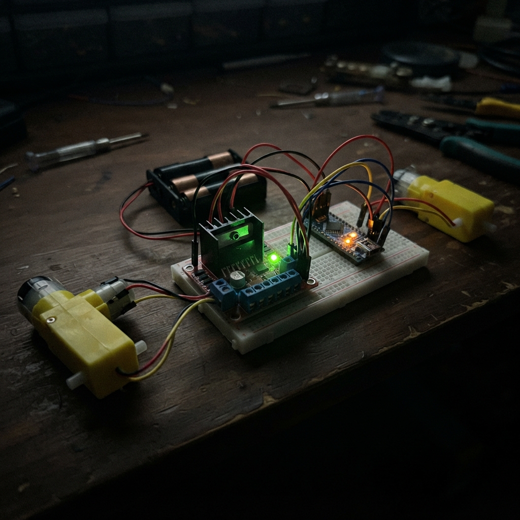
This guide builds a two-motor drive system using an Arduino Uno and an L298N motor controller to independently command left and right DC motors. The project demonstrates forward motion, stops, and reverse sequences—a foundation for mobile robotics, wheeled platforms, and autonomous vehicles.
The guide includes a complete wiring diagram showing how to connect both TT gearmotors to the L298N controller, a parts list with the 6V battery pack and all control leads, step-by-step assembly instructions with safety notes about keeping motor power separate, and ready-to-upload Arduino firmware that cycles through drive patterns. Test with wheels raised before deploying on the ground.
Wiring diagram

Gather all the parts
Assemble it in 6 steps
1. Keep the motor supply separate
Leave the 6V battery pack unplugged while wiring. Power the Arduino Uno from its USB socket later; use the 6V pack only for the L298N motor-power screw terminals.
- Find the L298N terminals marked VS or +12V and GND before inserting a wire.
- Do not connect the 6V motor battery to the Arduino 5V pin — the motors can pull too much current and reset or damage the board.
2. Connect the two motors
Connect the two wires from the left TT motor to L298N OUT1 and OUT2. Connect the two wires from the right TT motor to L298N OUT3 and OUT4. The wire order only chooses which way each wheel calls forward.
- Tighten the screw terminals gently so bare wire is clamped but the screw is not stripped.
- Keep the two bare wires from each motor apart — touching them together can heat the driver or battery wires.
3. Wire the Arduino control leads
Connect L298N ENA to Arduino D5 (left-motor speed), ENB to D6 (right-motor speed), IN1 to D7 (left direction), IN2 to D8 (left direction), IN3 to D12 (right direction), and IN4 to D13 (right direction). If your L298N board has small ENA and ENB jumper caps fitted, remove both caps before connecting D5 and D6 so the Arduino can control speed.
- Use six different wire colors or label the ends so each control wire is easy to trace.
- Do not put an ENA or ENB jumper cap back on while its matching Arduino pin is connected — it can force that control line high.
4. Make the shared ground connection
Connect an Arduino GND pin to L298N GND. Then connect the negative (−) wire from the 6V battery pack to that same L298N GND terminal; this shared connection lets the Arduino’s control signals be understood by the driver.
- Two wires may go into the L298N GND screw terminal; use a small terminal block if the terminal cannot safely clamp both wires.
- Without the Arduino GND-to-L298N GND wire, the motors may run unpredictably or not respond at all.
5. Connect the power wires last
Connect Arduino 5V to the L298N 5V logic pin. Connect the positive (+) wire of the 6V battery pack to L298N VS or +12V motor-power input, then connect its negative (−) wire to L298N GND. Finally plug the Arduino into USB.
- Read the printed labels on your exact L298N board: VS is often printed as +12V even when using a 6V motor battery.
- Make sure the battery + and − are not swapped — reversed battery power can damage the L298N module.
6. Test with the wheels raised
Hold the robot so both wheels are off the table, connect the 6V battery, and press Deploy in Schematik after the Arduino is connected by USB. The motors should go forward for two seconds, stop for one second, reverse for two seconds, then repeat.
- If one wheel turns the opposite way from the other, unplug the battery and swap only that motor’s two wires at its OUT terminals.
- Keep fingers, loose wires, hair, and clothing away from spinning wheels.
Review all connections
1. Connections between "battery_6v" and "Arduino"
2. Connections between "l298n_1" and "Arduino"
Deploy the firmware
#include <Arduino.h>
// Arduino Uno R3 + L298N + two 3–6V TT motors
// Demonstrates forward, stop, reverse, stop, then repeats.


// Forward declarations
void stopMotors();
void driveForward(uint8_t speedValue);
void driveReverse(uint8_t speedValue);

const uint8_t LEFT_EN = 5;
const uint8_t RIGHT_EN = 6;
const uint8_t LEFT_IN1 = 7;
const uint8_t LEFT_IN2 = 8;
const uint8_t RIGHT_IN1 = 12;
const uint8_t RIGHT_IN2 = 13;

const uint8_t DRIVE_SPEED = 200;  // 0 = stopped, 255 = full speed

void stopMotors() {
  analogWrite(LEFT_EN, 0);
  analogWrite(RIGHT_EN, 0);
  digitalWrite(LEFT_IN1, LOW);
  digitalWrite(LEFT_IN2, LOW);
  digitalWrite(RIGHT_IN1, LOW);
  digitalWrite(RIGHT_IN2, LOW);
}

void driveForward(uint8_t speedValue) {
  digitalWrite(LEFT_IN1, HIGH);
  digitalWrite(LEFT_IN2, LOW);
  digitalWrite(RIGHT_IN1, HIGH);
  digitalWrite(RIGHT_IN2, LOW);
  analogWrite(LEFT_EN, speedValue);
  analogWrite(RIGHT_EN, speedValue);
}

void driveReverse(uint8_t speedValue) {
  digitalWrite(LEFT_IN1, LOW);
  digitalWrite(LEFT_IN2, HIGH);
  digitalWrite(RIGHT_IN1, LOW);
  digitalWrite(RIGHT_IN2, HIGH);
  analogWrite(LEFT_EN, speedValue);
  analogWrite(RIGHT_EN, speedValue);
}

void setup() {
  pinMode(LEFT_EN, OUTPUT);
  pinMode(RIGHT_EN, OUTPUT);
  pinMode(LEFT_IN1, OUTPUT);
  pinMode(LEFT_IN2, OUTPUT);
  pinMode(RIGHT_IN1, OUTPUT);
  pinMode(RIGHT_IN2, OUTPUT);
  stopMotors();
}

void loop() {
  driveForward(DRIVE_SPEED);
  delay(2000);

  stopMotors();
  delay(1000);

  driveReverse(DRIVE_SPEED);
  delay(2000);

  stopMotors();
  delay(1000);
}
Remix this project
Make it yours in one click
Open a full copy of this project in your own Schematik workspace — diagram, code, parts, and assembly steps included. Swap the sensor, add features, or redesign the whole thing with AI. The author's original stays untouched.
Related projects
Joystick-Controlled Relay Switches
Arduino · September 21, 2026Mohamed Mediouni
Código Táctil Para Cerradura Segura
Arduino · September 20, 2026alvearuno
Ultrasonic Companion Robot
Arduino · September 20, 2026MUHAMMAD ISHAQ RAIF BIN NOR ISMAN Moe