Community project
Código Táctil Para Cerradura Segura
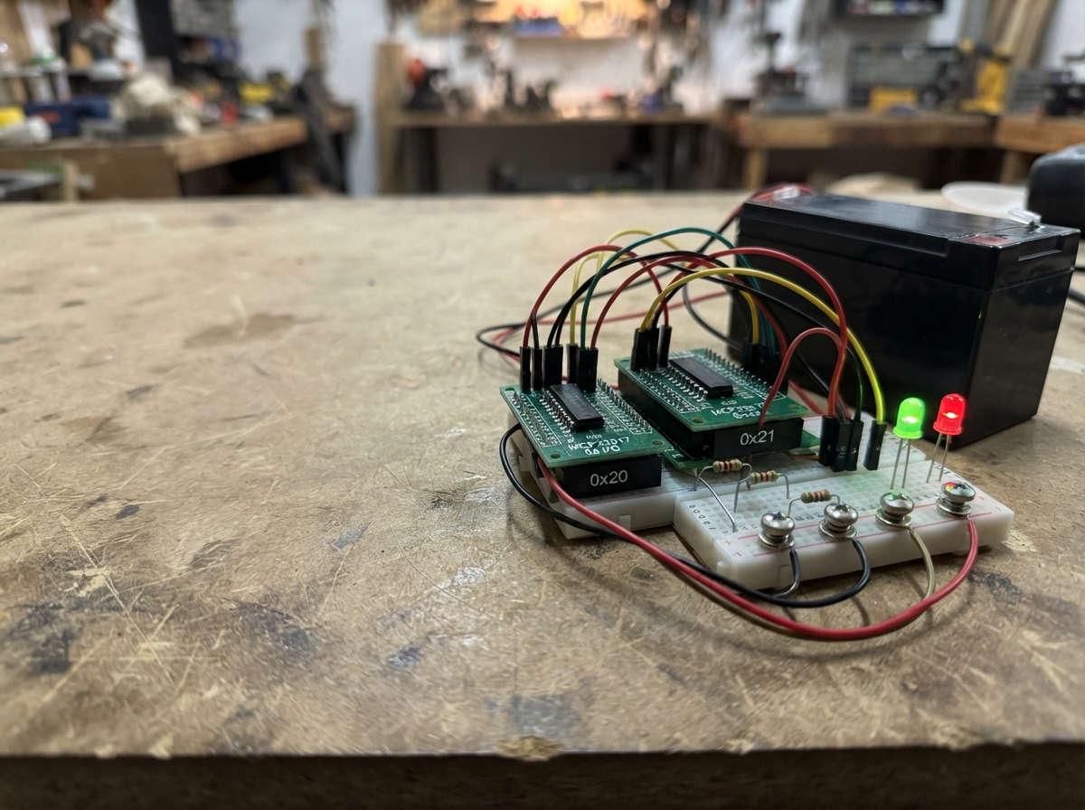
This project implements a secure door lock controlled by a capacitive touch code entry system. The system uses an Arduino Uno to read a three-digit code from an isolated touch electrode, then commands twelve high-current actuators through dual MCP23017 I/O expanders and IBT-2 motor drivers to mechanically lock or unlock the door. A 12V battery with fused distribution powers the actuators, while a buck converter supplies clean 5V to the control electronics.
This guide provides a complete wiring diagram, detailed parts list, and step-by-step assembly instructions for integrating the touch sensor, LED indicators, power distribution, and motor control circuits. The included Arduino firmware handles capacitive touch detection, code validation with visual feedback, and sequential actuator sequencing. Safety testing procedures ensure proper operation before final installation.
Wiring diagram
Gather all the parts
Assemble it in 8 steps
1. Fija los actuadores con la puerta abierta
Monta los doce actuadores lineales y sus herrajes con la puerta completamente abierta. Cada actuador debe poder llegar a sus propios finales de carrera sin forzar el cierre ni doblar la varilla.
- Etiqueta cada par de cables como A1 a A12 antes de llevarlos al cuadro de control.
- No pruebes un actuador instalado en una puerta cerrada hasta comprobar que su mecanismo no puede atrapar dedos ni bloquear una salida de emergencia.
2. Monta la batería y los fusibles
Con la batería desconectada, lleva el positivo de la batería de 12 V al portafusible principal de 30 A y de ahí a la entrada del bloque de doce fusibles. Lleva el negativo de la batería a una barra común de GND. Pon un fusible de 25 A en cada una de las doce salidas del bloque.
- Usa cable y terminales dimensionados para 25 A en cada ramal de actuador, y mantén el cable principal lo más corto posible.
- Un fusible de 30 A no protege doce actuadores contra una suma de corrientes: el programa mueve uno por vez, pero cada ramal debe conservar su fusible de 25 A.
3. Conecta los doce controladores de potencia
Conecta OUT1 a B+ de driver_1, OUT2 a B+ de driver_2, y continúa en el mismo orden hasta OUT12 y driver_12. Conecta B- y GND de todos los controladores a la barra común de GND. Conecta M+ y M- de cada driver al par de cables de su actuador con el mismo número.
- Si un actuador se mueve al revés en la prueba, desconecta la batería y cambia sólo sus dos cables M+ y M-.
- Nunca cambies cables M+ o M- con la batería conectada: un cortocircuito en esta zona puede quemar cableado o el controlador.
4. Alimenta la parte de 5 V
Conecta la entrada IN+ del convertidor a la salida protegida de 12 V después del fusible principal y su IN- a GND. Ajusta y verifica primero que OUT+ entrega exactamente 5 V. Después conecta OUT+ al rail de 5 V y OUT- a GND; ese rail alimenta el Arduino, los dos MCP23017 y VCC, R_EN y L_EN de cada BTS7960.
- Todas las masas GND —batería, convertidor, Arduino, expansores y controladores— deben quedar unidas para que las órdenes tengan referencia común.
- No lleves 12 V al Arduino, a los expansores MCP23017 ni a los pines VCC de los BTS7960: sólo deben recibir 5 V.
5. Conecta el Arduino, los expansores y los LED
Conecta SDA de ambos MCP23017 a A4 del Arduino y SCL de ambos a A5. Conecta VDD a 5 V y VSS a GND. Conecta D3 a la resistencia de 220 Ω del LED verde y la resistencia al ánodo; conecta el cátodo a GND. Conecta D4 a la resistencia de 220 Ω del LED rojo y la resistencia al ánodo; conecta el cátodo a GND.
- A4 → SDA (datos), A5 → SCL (reloj), D3 → resistencia → LED verde (aviso), D4 → resistencia → LED rojo (error).
- No conectes un LED directamente a D3 o D4: la resistencia de 220 Ω evita que el LED y el Arduino se dañen.
6. Conecta las 24 órdenes de los controladores
En expansor_salidas_1 conecta P0/P1 a RPWM/LPWM de driver_1, P2/P3 a driver_2, y continúa por parejas hasta P14/P15 para driver_8. En expansor_salidas_2 conecta P0/P1 a driver_9, P2/P3 a driver_10, P4/P5 a driver_11 y P6/P7 a driver_12.
- RPWM y LPWM son las dos órdenes de sentido; el programa deja una a cero antes de encender la otra, y sólo activa un driver cada vez.
- No unas RPWM y LPWM del mismo controlador entre sí: recibir órdenes contrarias puede dañar el controlador o causar un frenado brusco.
7. Monta el tornillo táctil aislado
Sujeta el tornillo donde se vaya a tocar, aislándolo eléctricamente del marco metálico. Conecta D7 a un extremo de la resistencia de 1 MΩ; conecta el otro extremo de la resistencia al tornillo. Conecta también el tornillo directamente a D8.
- D7 → resistencia de 1 MΩ → tornillo (medida segura); tornillo → D8 (lectura del toque).
- Si el tornillo toca una parte metálica conectada a tierra, la detección puede fallar; mantén aislada la zona que se toca.
8. Prueba con seguridad antes de cerrar la puerta
Enciende primero sin conectar los cables M+ y M- de los actuadores y confirma los LED. Después conecta un solo actuador, prueba abrir y cerrar con la puerta abierta y confirma el sentido. Por último conecta los demás, manteniendo libre la zona de movimiento.
- La clave de apertura inicial es 1-2-3 y la de cierre inicial es 3-2-1; ambas se pueden cambiar al comienzo del código.
- Antes de usarlo como cierre real, comprueba que la puerta siempre se pueda abrir desde el interior y que el fallo de alimentación no cree un riesgo para personas.
Review all connections
1. Connections between "placa_tactil" and "Arduino"
2. Connections between "resistor_tacto" and "Arduino"
3. Connections between "resistor_led_verde" and "Arduino"
4. Connections between "led_verde_estado" and "Arduino"
5. Connections between "resistor_led_rojo" and "Arduino"
6. Connections between "led_rojo_error" and "Arduino"
7. Connections between "expansor_salidas_1" and "Arduino"
8. Connections between "expansor_salidas_2" and "Arduino"
9. Connections between "bateria_12v" and "Arduino"
10. Connections between "fusible_principal_30a" and "Arduino"
11. Connections between "convertidor_12a5v" and "Arduino"
12. Connections between "bloque_fusibles_12v" and "Arduino"
13. Connections between "driver_1" and "Arduino"
14. Connections between "driver_2" and "Arduino"
15. Connections between "driver_3" and "Arduino"
16. Connections between "driver_4" and "Arduino"
17. Connections between "driver_5" and "Arduino"
18. Connections between "driver_6" and "Arduino"
19. Connections between "driver_7" and "Arduino"
20. Connections between "driver_8" and "Arduino"
21. Connections between "driver_9" and "Arduino"
22. Connections between "driver_10" and "Arduino"
23. Connections between "driver_11" and "Arduino"
24. Connections between "driver_12" and "Arduino"
Deploy the firmware
#include <Arduino.h>
#include <Wire.h>
#include <CapacitiveSensor.h>
#include <Adafruit_MCP23X17.h>

enum SystemState { IDLE, READY_PATTERN, ENTERING_CODE, DIGIT_FLASH, SUCCESS_PATTERN, ERROR_PATTERN, MOVING_ACTUATORS };
enum RequestedAction { NO_ACTION, OPEN_DOOR, CLOSE_DOOR };


// Forward declarations
void setGreenBrightness(byte brightness);
void lightsOff();
void resetEntry();
void writeExpanderPin(byte actuator, bool reverse, bool value);
void stopAllActuators();
void startOneActuator(byte actuator, bool useRPWM);
bool codeMatches(const byte expected[3]);
void startReadyPattern();
void beginCodeEntry();
void finishDigit();
void registerTap();
void startSequentialMovement();
void updateMotion();
void updateIndicatorsAndState();

const byte GREEN_LED_PIN = 3;
const byte RED_LED_PIN = 4;
const byte TOUCH_SEND_PIN = 7;
const byte TOUCH_RECEIVE_PIN = 8;

// ===== AJUSTES DE TOQUES Y TIEMPOS: MODIFÍCALOS AQUÍ =====
// Tiempo mínimo entre dos toques que cuentan como toques distintos de una cifra.
const unsigned long MIN_TIME_BETWEEN_TAPS_MS = 350;
// Tiempo máximo sin tocar que termina una cifra y permite pasar a la siguiente.
const unsigned long MAX_TIME_BETWEEN_TAPS_MS = 1800;
// Tiempo máximo total para introducir las tres cifras una vez activado el teclado.
const unsigned long CODE_ENTRY_TIMEOUT_MS = 10000;

// Primer aviso verde: encendido 500 ms, apagado 500 ms, encendido 500 ms.
const unsigned long READY_PATTERN_MS = 1500;
const unsigned long DIGIT_FLASH_MS = 250;
const unsigned long ERROR_PATTERN_MS = 2000;
const unsigned long SUCCESS_PATTERN_MS = 3000;

// ===== CLAVES DE ACCESO: MODIFÍCALAS AQUÍ =====
// Cada número es el número de toques de una cifra. Ejemplo {1,2,3} = toque, pausa;
// dos toques, pausa; tres toques. Cada cifra debe estar entre 1 y 9.
const byte openCode[3] = {1, 2, 3};   // Clave que ABRE los 12 cierres.
const byte closeCode[3] = {3, 2, 1};  // Clave que CIERRA los 12 cierres.

// ===== MOVIMIENTO DE LOS ACTUADORES: MODIFÍCALO SÓLO TRAS UNA PRUEBA MECÁNICA =====
// El máximo por actuador es 15 s. Los actuadores con final de carrera interno se detienen antes.
const unsigned long ACTUATOR_MAX_RUN_MS = 15000;
// Pausa sin corriente entre un actuador y el siguiente.
const unsigned long BETWEEN_ACTUATORS_MS = 300;
// Cambia false por true si la dirección RPWM resulta ser la de abrir al probar el actuador 1.
const bool OPEN_USES_RPWM = false;

const unsigned long TOUCH_THRESHOLD = 800;
const byte EXPANDER_1_ADDRESS = 0x20;
const byte EXPANDER_2_ADDRESS = 0x21;
const byte ACTUATOR_COUNT = 12;

CapacitiveSensor touchSensor(TOUCH_SEND_PIN, TOUCH_RECEIVE_PIN);
Adafruit_MCP23X17 expander1;
Adafruit_MCP23X17 expander2;

SystemState state = IDLE;
RequestedAction pendingAction = NO_ACTION;
byte enteredDigits[3];
byte digitCount = 0;
byte tapsForDigit = 0;
byte currentActuator = 0;
bool actuatorEnergized = false;
bool touchWasDetected = false;
unsigned long lastTouchMs = 0;
unsigned long lastTapMs = 0;
unsigned long stateStartedMs = 0;
unsigned long entryStartedMs = 0;
unsigned long motionStartedMs = 0;

void setGreenBrightness(byte brightness) { analogWrite(GREEN_LED_PIN, brightness); }
void lightsOff() { setGreenBrightness(0); digitalWrite(RED_LED_PIN, LOW); }

void resetEntry() {
  digitCount = 0;
  tapsForDigit = 0;
  lastTapMs = 0;
}

void writeExpanderPin(byte actuator, bool reverse, bool value) {
  // Actuadores 1..7: MCP23017 #1, P0..P13. Actuadores 8..12: MCP23017 #2, P0..P9.
  Adafruit_MCP23X17 *expander = (actuator < 7) ? &expander1 : &expander2;
  byte localActuator = (actuator < 7) ? actuator : actuator - 7;
  byte pin = localActuator * 2 + (reverse ? 1 : 0);
  expander->digitalWrite(pin, value ? HIGH : LOW);
}

void stopAllActuators() {
  for (byte i = 0; i < ACTUATOR_COUNT; i++) {
    writeExpanderPin(i, false, false);
    writeExpanderPin(i, true, false);
  }
}

void startOneActuator(byte actuator, bool useRPWM) {
  // Primero se apagan todas las salidas: nunca se permiten dos actuadores a la vez.
  stopAllActuators();
  writeExpanderPin(actuator, !useRPWM, false);
  writeExpanderPin(actuator, useRPWM, true);
}

bool codeMatches(const byte expected[3]) {
  for (byte i = 0; i < 3; i++) {
    if (enteredDigits[i] != expected[i]) return false;
  }
  return true;
}

void startReadyPattern() {
  resetEntry();
  lightsOff();
  state = READY_PATTERN;
  stateStartedMs = millis();
}

void beginCodeEntry() {
  lightsOff();
  resetEntry();
  state = ENTERING_CODE;
  entryStartedMs = millis();
}

void finishDigit() {
  if (tapsForDigit == 0) return;
  if (tapsForDigit > 9 || digitCount >= 3) {
    state = ERROR_PATTERN;
    stateStartedMs = millis();
    resetEntry();
    return;
  }

  enteredDigits[digitCount++] = tapsForDigit;
  tapsForDigit = 0;
  if (digitCount < 3) {
    state = DIGIT_FLASH;
    stateStartedMs = millis();
  } else if (codeMatches(openCode)) {
    pendingAction = OPEN_DOOR;
    state = SUCCESS_PATTERN;
    stateStartedMs = millis();
  } else if (codeMatches(closeCode)) {
    pendingAction = CLOSE_DOOR;
    state = SUCCESS_PATTERN;
    stateStartedMs = millis();
  } else {
    pendingAction = NO_ACTION;
    state = ERROR_PATTERN;
    stateStartedMs = millis();
  }
}

void registerTap() {
  unsigned long now = millis();
  if (now - lastTouchMs < MIN_TIME_BETWEEN_TAPS_MS) return;
  lastTouchMs = now;
  if (state == IDLE) startReadyPattern();
  else if (state == ENTERING_CODE) {
    tapsForDigit++;
    lastTapMs = now;
  }
}

void startSequentialMovement() {
  currentActuator = 0;
  actuatorEnergized = true;
  bool useRPWM = (pendingAction == OPEN_DOOR) ? OPEN_USES_RPWM : !OPEN_USES_RPWM;
  startOneActuator(currentActuator, useRPWM);
  motionStartedMs = millis();
  state = MOVING_ACTUATORS;
}

void updateMotion() {
  unsigned long now = millis();
  if (actuatorEnergized && now - motionStartedMs >= ACTUATOR_MAX_RUN_MS) {
    stopAllActuators();
    actuatorEnergized = false;
    motionStartedMs = now;
  } else if (!actuatorEnergized && now - motionStartedMs >= BETWEEN_ACTUATORS_MS) {
    currentActuator++;
    if (currentActuator >= ACTUATOR_COUNT) {
      pendingAction = NO_ACTION;
      startReadyPattern();
    } else {
      bool useRPWM = (pendingAction == OPEN_DOOR) ? OPEN_USES_RPWM : !OPEN_USES_RPWM;
      startOneActuator(currentActuator, useRPWM);
      actuatorEnergized = true;
      motionStartedMs = now;
    }
  }
}

void updateIndicatorsAndState() {
  unsigned long elapsed = millis() - stateStartedMs;
  if (state == READY_PATTERN) {
    setGreenBrightness((elapsed < 500 || (elapsed >= 1000 && elapsed < 1500)) ? 255 : 0);
    if (elapsed >= READY_PATTERN_MS) beginCodeEntry();
  } else if (state == DIGIT_FLASH) {
    setGreenBrightness(255);
    if (elapsed >= DIGIT_FLASH_MS) {
      lightsOff();
      state = ENTERING_CODE;
    }
  } else if (state == SUCCESS_PATTERN) {
    unsigned long phase = elapsed % 1000;
    byte brightness = (phase < 500) ? map(phase, 0, 499, 0, 255) : map(phase, 500, 999, 255, 0);
    setGreenBrightness(brightness);
    if (elapsed >= SUCCESS_PATTERN_MS) {
      lightsOff();
      startSequentialMovement();
    }
  } else if (state == ERROR_PATTERN) {
    // Cuatro destellos completos en 2 s: 250 ms encendido y 250 ms apagado cada vez.
    digitalWrite(RED_LED_PIN, (elapsed % 500) < 250 ? HIGH : LOW);
    if (elapsed >= ERROR_PATTERN_MS) {
      lightsOff();
      startReadyPattern();
    }
  } else if (state == MOVING_ACTUATORS) updateMotion();
}

void setup() {
  pinMode(GREEN_LED_PIN, OUTPUT);
  pinMode(RED_LED_PIN, OUTPUT);
  lightsOff();
  touchSensor.set_CS_AutocaL_Millis(0xFFFFFFFF);

  Wire.begin();
  expander1.begin_I2C(EXPANDER_1_ADDRESS);
  expander2.begin_I2C(EXPANDER_2_ADDRESS);
  // El primer expansor usa P0..P13 (actuadores 1 a 7); P14 y P15 quedan libres.
  for (byte pin = 0; pin < 14; pin++) expander1.pinMode(pin, OUTPUT);
  // El segundo usa P0..P9 (actuadores 8 a 12).
  for (byte pin = 0; pin < 10; pin++) expander2.pinMode(pin, OUTPUT);
  stopAllActuators();
}

void loop() {
  long sensorValue = touchSensor.capacitiveSensor(20);
  bool touching = sensorValue > TOUCH_THRESHOLD;
  if (touching && !touchWasDetected) registerTap();
  touchWasDetected = touching;

  if (state == ENTERING_CODE) {
    if (tapsForDigit > 0 && millis() - lastTapMs >= MAX_TIME_BETWEEN_TAPS_MS) finishDigit();
    if (millis() - entryStartedMs >= CODE_ENTRY_TIMEOUT_MS) {
      lightsOff();
      resetEntry();
      state = IDLE;
    }
  }
  updateIndicatorsAndState();
}
Remix this project
Make it yours in one click
Open a full copy of this project in your own Schematik workspace — diagram, code, parts, and assembly steps included. Swap the sensor, add features, or redesign the whole thing with AI. The author's original stays untouched.
Related projects
Joystick-Controlled Relay Switches
Arduino · September 21, 2026Mohamed Mediouni
Dual-Motor Drive Control
Arduino · September 20, 2026ศุภชัย ราชผึ้ง
Ultrasonic Companion Robot
Arduino · September 20, 2026MUHAMMAD ISHAQ RAIF BIN NOR ISMAN Moe