Community project
Temperature Humidity Alert Display
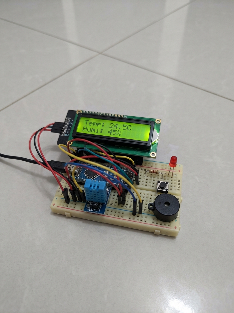
This project builds a temperature and humidity monitoring station that displays real-time sensor readings on an LCD screen and alerts the user when conditions exceed preset thresholds. The ESP32 microcontroller reads data from a DHT11 sensor, shows the values on a 16x2 I2C LCD display, and triggers a red LED and buzzer alarm when temperature or humidity goes out of range. A MODE button lets users cycle through different alert thresholds or display modes.
The guide includes a complete wiring diagram showing how to connect the DHT11 module, LCD backpack, button, LED with current-limiting resistor, and buzzer to the ESP32 pins. You'll also get a parts list, step-by-step assembly instructions for breadboard layout, and firmware code to read the sensor, manage the display, and control the alerts.
Wiring diagram

Gather all the parts
Assemble it in 7 steps
1. Set up the power rails
Place the ESP32-S3 DevKitC-1 beside the breadboard with its USB connector accessible. Use only the upper left-hand half of the red rail and the blue rail beside it. Run one red jumper from the board’s 3V3 pin to that red rail, and one black jumper from a board GND pin to the blue rail. The red rail has a break in its middle, so do not assume its other half has power.
- Treat the chosen red rail segment as 3.3 V only; do not connect the board’s 5 V pin to it.
- The blue rail is the shared return path for every part.
- Do not bridge the two red-rail halves by accident; the far half is intentionally unused.
- Make sure 3V3 and GND are not swapped — swapped power can damage the LCD and sensor.
2. Place and wire the LCD
Insert the LCD backpack’s four header pins into rows A2 through A5 in this order: GND at A2, VCC at A3, SDA at A4, and SCL at A5. Use a black jumper from A2 to the blue rail, a red jumper from A3 to the powered left red rail, a jumper from ESP32-S3 GPIO8 to A4, and a jumper from ESP32-S3 GPIO9 to A5. This is the only LCD: use its four-pin I2C backpack, not the LCD’s 16-pin parallel header.
- If the LCD is attached by loose jumper wires rather than inserted directly, still use A2, A3, A4, and A5 as the breadboard landing rows.
- The backpack address is 0x27, matching the existing sketch.
- Power the LCD VCC from 3.3 V, not 5 V — a 5 V I2C pull-up can damage ESP32-S3 GPIO pins.
3. Place and wire the DHT11 module
Insert the DHT11 module so its pins marked +, -, and S land in A8, A9, and A10 respectively. Run A8 to the powered left red rail, A9 to the blue rail, and a jumper from A10 to ESP32-S3 GPIO13. Do not add a pull-up resistor.
- Read the labels printed on the module rather than relying only on pin position; DHT11 modules can be arranged differently by brand.
- Keep the DHT11 on 3.3 V; do not connect its + pin to 5 V.
4. Place the MODE button across the center gap
Push the tactile button across the breadboard’s center gap so its top-right leg is in J14 and its bottom-left leg is in A16. Run a jumper from ESP32-S3 GPIO4 to J14 and a black jumper from A16 to the blue rail. J14 and A16 are deliberately different rows, and the sketch’s built-in pull-up handles the button without an external resistor.
- The button must straddle the center gap; if all four legs sit on one side, its legs can be shorted together by the breadboard.
- This placement leaves rows 24 and 25 free for the buzzer.
- Do not put both button jumpers in the same numbered row, or the button will not work as intended.
5. Place the red LED and its resistor
Put the LED long leg in D20 and the short leg in D21 so the legs are in different numbered rows. Run a jumper from ESP32-S3 GPIO5 to D20. Put one end of the 220 ohm resistor into D21 with the LED short leg and put its other end into the blue rail. The resistor may face either direction.
- The LED’s long leg is the positive side. The short leg, often beside a flat edge on the LED body, is the negative side.
- If the LED does not light, unplug USB power and turn the LED around; it is polarity-sensitive.
- Do not connect the LED directly between GPIO5 and ground — the 220 ohm resistor is needed to prevent excessive current.
6. Place the passive buzzer on its own rows
Place the passive buzzer’s + pin in F24 and its other pin in F25. Run a jumper from ESP32-S3 GPIO18 to F24 and a black jumper from F25 to the blue rail. These rows are separate from the button rows.
- Use the + marking on the buzzer for F24. A passive buzzer needs the existing sketch to generate a tone.
- Do not share rows 24 or 25 with the MODE button wiring; shared rows would electrically join unrelated signals.
7. Check every connection before power
Before plugging in USB, confirm the only board signal wires are GPIO13 to DHT11 S at A10, GPIO8 to LCD SDA at A4, GPIO9 to LCD SCL at A5, GPIO4 to the button at J14, GPIO5 to LED long leg at D20, and GPIO18 to buzzer + at F24. Confirm all grounds reach the same blue rail and both the LCD and DHT11 reach the powered left red rail.
- GPIO19 and GPIO20 are untouched for USB, and GPIO22 is not used.
- The existing sketch is retained; this build changes no firmware.
- If a power wire is uncertain, unplug USB before moving it — incorrect power wiring can damage a module.
Review all connections
1. Connections between "dht11_1" and "ESP32"
2. Connections between "lcd1602_i2c_1" and "ESP32"
3. Connections between "mode_button_1" and "ESP32"
4. Connections between "red_led_1" and "ESP32"
5. Connections between "resistor_220_1" and "ESP32"
6. Connections between "passive_buzzer_1" and "ESP32"
Remix this project
Make it yours in one click
Open a full copy of this project in your own Schematik workspace — diagram, code, parts, and assembly steps included. Swap the sensor, add features, or redesign the whole thing with AI. The author's original stays untouched.