Community project
WiFi Button Status Monitor
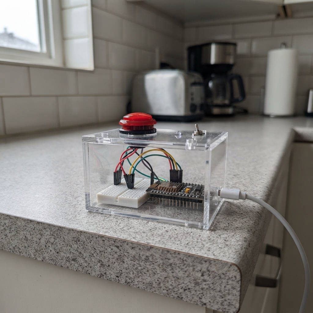
This project turns an ESP32 into a simple WiFi-connected button monitor that displays the current state of a push button through a web interface. The device creates its own WiFi access point, allowing any device on the network to check whether the button is pressed or released in real time.
The guide includes a wiring diagram showing how to connect the push button to pin D6, a complete parts list, and the firmware needed to get the web server running. Assembly takes just minutes: wire the button, power up the board, connect to the WiFi network, and open a browser to view the button status refreshing every second.
Wiring diagram

Gather all the parts
Assemble it in 3 steps
1. Unplug the board
Unplug the NodeMCU ESP8266 board from USB before changing the wires so you cannot accidentally short a pin.
- The board label D6 means GPIO12 in the firmware.
- Do not use the old ESP32 GPIO21 connection; GPIO21 does not exist on this ESP8266 board.
2. Wire the button to D6
Connect one button leg to the NodeMCU pin marked D6, which is GPIO12 (signal). Connect the opposite button leg to any GND pin (ground). When pressed, the button connects D6 to ground.
- For a four-leg tactile button, use legs from opposite sides of the button; the two legs on one side are already connected together.
- No added resistor is needed because the program holds the input safely high until the button is pressed.
- Make sure the button goes only between D6 and GND — connecting it to 3V3 can make the status read incorrectly.
3. Power it and view the status
Plug the NodeMCU into USB, then press Deploy in Schematik. Connect your phone or computer to the Wi-Fi network Button-Monitor using password pressrelease, then open http://192.168.4.1/ to see the simple button status page.
- The page updates once per second and shows PRESSED or RELEASED.
- This creates a small Wi-Fi network from the board; it is separate from your usual home Wi-Fi.
Review all connections
1. Connections between "button_1" and "ESP32"
Deploy the firmware
#include <Arduino.h>
#include <ESP8266WiFi.h>
#include <ESP8266WebServer.h>


// Forward declarations
void sendPage();

const uint8_t BUTTON_PIN = 12;  // D6
const char *AP_SSID = "Button-Monitor";
const char *AP_PASSWORD = "pressrelease";

ESP8266WebServer server(80);
bool buttonPressed = false;

void sendPage() {
  const char *state = buttonPressed ? "PRESSED" : "RELEASED";
  String page = "<!doctype html><html><head>"
                "<meta name='viewport' content='width=device-width,initial-scale=1'>"
                "<meta http-equiv='refresh' content='1'>"
                "<title>Button</title></head><body>"
                "<h1>Button status</h1><h2>";
  page += state;
  page += "</h2><p>Refreshes every second.</p></body></html>";
  server.send(200, "text/html", page);
}

void setup() {
  pinMode(BUTTON_PIN, INPUT_PULLUP);
  WiFi.mode(WIFI_AP);
  WiFi.softAP(AP_SSID, AP_PASSWORD);
  server.on("/", sendPage);
  server.begin();
}

void loop() {
  buttonPressed = (digitalRead(BUTTON_PIN) == LOW);
  server.handleClient();
}
Remix this project
Make it yours in one click
Open a full copy of this project in your own Schematik workspace — diagram, code, parts, and assembly steps included. Swap the sensor, add features, or redesign the whole thing with AI. The author's original stays untouched.